One Community
Ultimate Classroom Straw Bale Construction Footers, Foundation, and Flooring
This page is about the excavation and construction details of the footer, foundation, and flooring for the straw bale construction Ultimate Classroom component of the Highest Good Education program. What we learn from this straw bale construction process will be further applied and refined as we build the Straw Bale Village (Pod 2).
As part of One Community Global’s commitment to sharing sustainable, DIY-replicable solutions, this tutorial provides detailed steps and considerations for anyone interested in replicating this innovative structure.
The report covers essential aspects of foundation and flooring design, including site preparation, material selection, and the installation process. Each phase is meticulously outlined to ensure clarity and replicability, while maintaining the structural integrity needed to support a versatile and dynamic educational space. The emphasis on sustainable building practices also ensures that the construction methods align with modern environmental goals.
By open-sourcing this tutorial, we aim to empower builders, educators, and sustainability advocates to create functional, resilient, and environmentally conscious learning spaces. Whether used for community projects, schools, or other educational spaces, the Ultimate Classroom foundation and flooring system sets a new standard for adaptable and replicable designs.
This guide consists of the following sections:
- What Is the Ultimate Classroom
- Why Open Source the Ultimate Classroom Foundation and Flooring
- Consultants of the Ultimate Classroom
- Energy EfficiencyProject Location
- Objectives
- Summary of Relevant Codes
- Foundation Types
- Compliance Strategy
- Design Criteria
- Material Properties
- Foundation Design
- Footers
- Foundation Types
- Regulatory Compliance
- Flooring Design
- Floor Insulation
- AutoCAD Plans
- Step-by-Step Tutorial & Construction Methodology
- Safety Measures for the Ultimate Classroom Construction Site
- Site Preparation
- Formwork and Reinforcement
- Foundation Construction
- Flooring System
- Rockwool Insulation
NOTE: THIS PAGE IS NOT CONSIDERED BY US TO BE A COMPLETE AND USABLE TUTORIAL UNTIL WE FINISH CONSTRUCTION AND ADD ALL THE VIDEOS AND EXPERIENCE FROM THE BUILD TO THIS PAGE – IN THE MEANTIME, WE WELCOME YOUR INPUT AND FEEDBACK
HERE ARE LINKS TO WHO WE ARE AS AN ORGANIZATION (click icons for complete pages)






VISIT THESE DETAILED PAGES FOR MORE ON THE COMPLETE VILLAGE PLANS (click icons)




WHAT IS THE ULTIMATE CLASSROOM
The Ultimate Classroom is a DIY-replicable straw bale construction classroom designed for use during the development of phases 1 and 2 of the One Community Global sustainability project.
This innovative structure will serve as a recreation and adult-education space when not being used as an early-education classroom. Feel free to double-click on the video below for a quick tour.
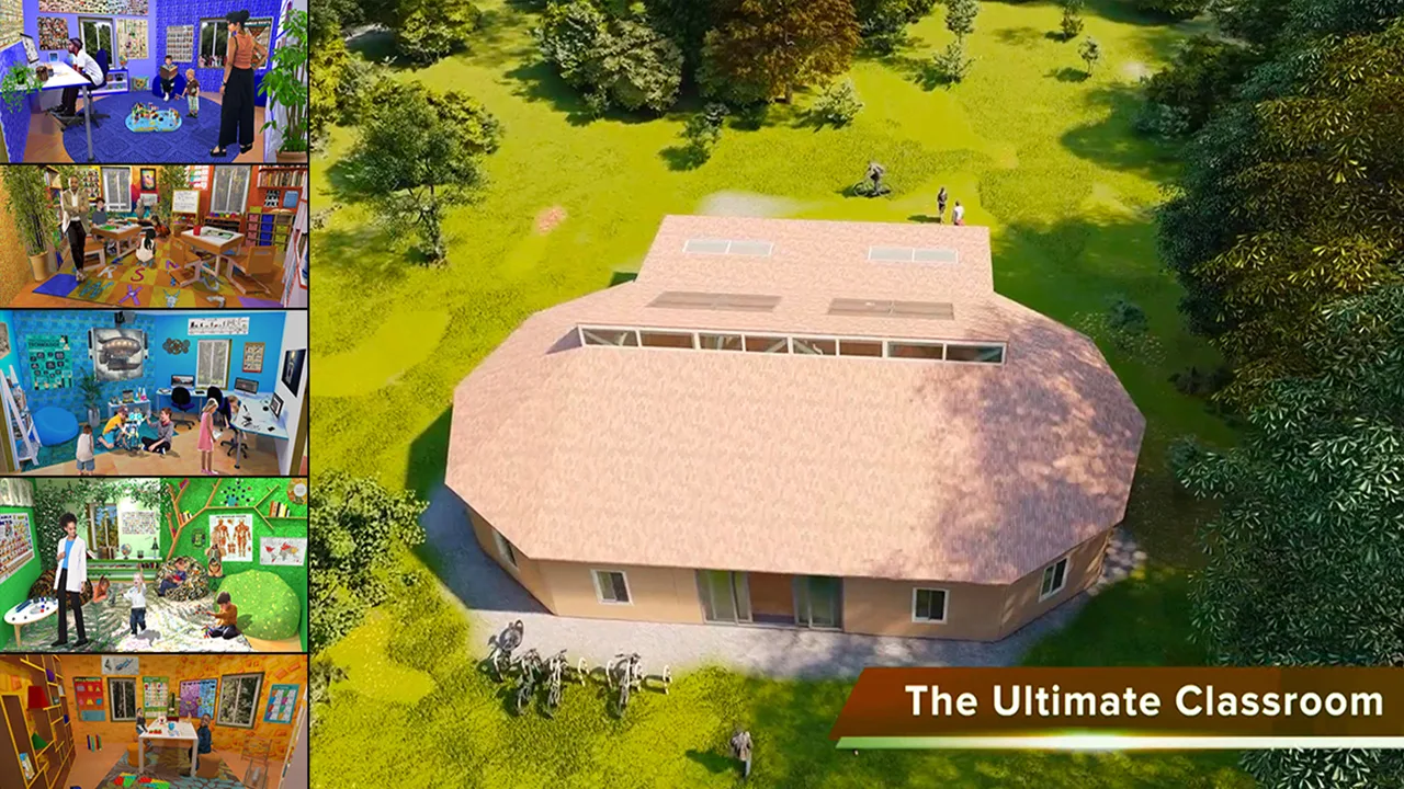
The Ultimate Classroom – Click for open source hub page
WHY OPEN SOURCE THE ULTIMATE CLASSROOM FOUNDATION AND FLOORING
 One of the core principles of One Community Global is to make sustainable solutions accessible to everyone by open-sourcing designs and methodologies. By providing detailed, DIY-replicable blueprints, we empower individuals and communities to implement sustainable practices on their own. The open-sourcing of the Ultimate Classroom Foundation and Flooring follows this ethos, offering a path for global adoption while providing a deeper understanding of sustainable building techniques.
In this context, open-sourcing the foundation and flooring system allows people to replicate a robust, environmentally conscious structure tailored for educational spaces. The design provides insight into foundational techniques suitable for straw bale construction, while emphasizing efficiency, durability, and adaptability. The foundation is essential not only for supporting the structure but also for ensuring the building’s long term stability in various climates and conditions, making it a key area of focus in sustainable construction efforts.
By sharing these resources freely, One Community Global contributes to a larger goal of global sustainability. It allows anyone, from individuals to organizations, to adapt and scale these designs according to their needs. This open-source model accelerates progress toward sustainable living and reinforces the idea that impactful change can be achieved through shared knowledge and collaborative efforts.
WAYS TO CONTRIBUTE TO EVOLVING THIS SUSTAINABILITY COMPONENT WITH US
SUGGESTIONS | CONSULTING | MEMBERSHIP | OTHER WAYS TO HELP
CONSULTANTS FOR THIS EDUCATION PROGRAM
Apoorv Pandey: Mechanical Engineer
Brian Muigai Mwaniki: Civil/Structural Engineer
Brian Mwoyowatidi: Graduate Structural Engineer
PROJECT LOCATION
The Ultimate Classroom project is designed to cover a broad geographical and environmental range, from the highest desert region of Utah at an elevation of 6000 feet to the coastal and urban areas of Southern California. This range accounts for extreme weather conditions, including the high snow loads and cold temperatures of Utah’s elevated desert regions, as well as the heat and seismic loads associated with Southern California. Shown below is a geographical map of the range discussed.
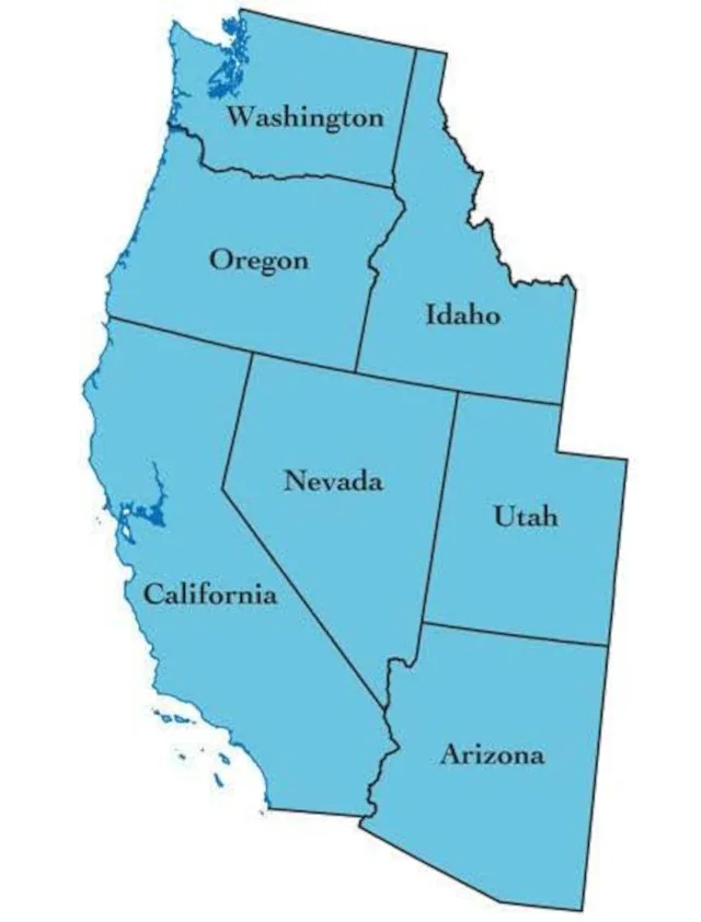
Ultimate Classroom Climate Design Range – Geographic map illustrating the environmental conditions, elevations, and structural design considerations from Utah’s high desert to Southern California.
The design of the foundation and flooring is intended to withstand both extremes, ensuring that the structure can adapt to a wide variety of climates and elevations. While we reference the high desert conditions near Utah, the project’s design is flexible enough to apply to any similar conditions in both regions.
By considering both high-elevation Utah and Southern California, the structural requirements for the Ultimate Classroom account for seismic activity, particularly in California, where seismic loads are more significant. Additionally, the HVAC system must be able to handle the cold loads in Utah’s high desert and the heat loads typical of Southern California. This dual-purpose design ensures that the building can provide a safe, comfortable, and resilient learning environment regardless of its specific location within this broad range.
ENERGY EFFICIENCY
The design meets California’s energy efficiency standards, Title 24, with considerations for renewable energy sources.
OBJECTIVES
The primary objective is to develop a compliant and robust design for the Ultimate Classroom’s footers, foundations, and flooring. Secondary goals include making the design replicable and accessible to promote the adoption of straw bale construction.
Comprehensive resources will demonstrate a clear path for replicating all aspects of The Ultimate Classroom, aiding builders with little to no experience in sustainable construction.
REGULATORY STANDARDS
The Ultimate Classroom project adheres to California’s CALGreen standards, which set the foundation for sustainable construction practices. CALGreen, the first mandatory green building standards code in the nation, aims to reduce environmental impact through efficient use of resources, improved indoor air quality, and overall enhancement of building performance.
By following CALGreen guidelines, the project ensures not only regulatory compliance but also promotes sustainability and energy efficiency in the construction process.
SUMMARY OF RELEVANT CODES
Adhering to building codes is essential to ensure the safety, durability, and functionality of any structure. For the Ultimate Classroom, compliance with relevant codes such as the California Building Standards Code, Title 24, and ACI 318-2019 guarantees that the foundation and flooring system meet established safety, structural, and environmental requirements.
GENERAL REQUIREMNTS
Here we look at the key building codes and standards that guide the construction process. These codes ensure that the foundation and flooring system meet safety, durability, and environmental sustainability criteria. In alignment with both state and national standards, this section will summarize essential practices from codes such as the CALGreen Building Code, ACI 318-2019 for structural concrete, and the International Building Code (IBC), among others.
Understanding these codes is critical to ensuring the Ultimate Classroom not only meets regulatory standards but also aligns with best practices for structural integrity, seismic safety, load-bearing capacity, and energy efficiency. This section will serve as a foundation for more detailed guidelines and design criteria that follow in the report.
DESIGN PRINCIPLES
Our foundation design ensures safety, serviceability, and structural integrity under all anticipated loads, including dead, live, wind, seismic, and other environmental forces.
MATERIALS
We have selected concrete and reinforcing materials that meet high standards for durability and strength.
FOUNDATION TYPES
Foundations are the unsung heroes of every structure, bearing the weight of innovation and sustainability from the ground up. With a variety of options available – such as shallow foundations like spread footings and slab-on-grade, or deep foundations like piles and drilled shafts – the choice reflects the unique demands of each project.
For the Ultimate Classroom, we’ve embraced a shallow-foundation design, prioritizing efficiency, adaptability, and simplicity. This approach aligns perfectly with the project’s sustainability goals, ensuring a durable and replicable base for this groundbreaking educational space.
- Shallow Foundations: Our design includes isolated spread footings that distribute loads to the soil without exceeding its bearing capacity, minimizing settlement.
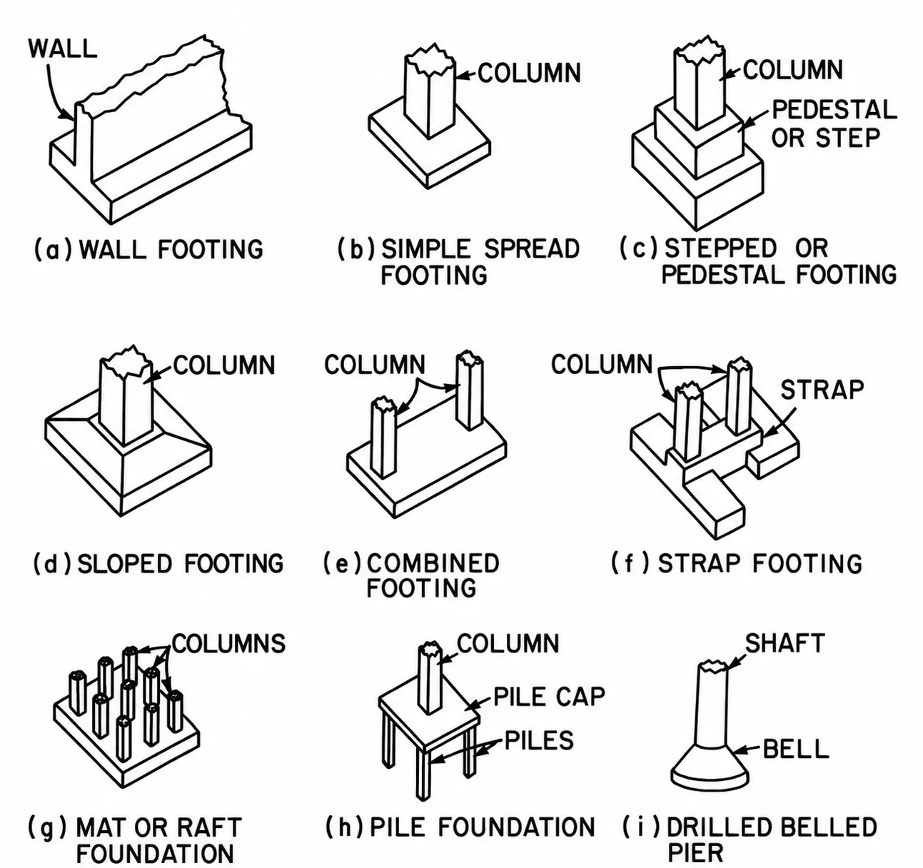
FOOTING
The footing design prioritizes stability tailored to the specific load demands and soil bearing capacity.
- Footing Design: The footings are designed to prevent shear and bending failures, with sizes and reinforcement determined based on applied loads and soil bearing capacity.
- Reinforcement: Adequate reinforcement has been provided to handle bending moments and shear forces, ensuring the foundation’s performance.
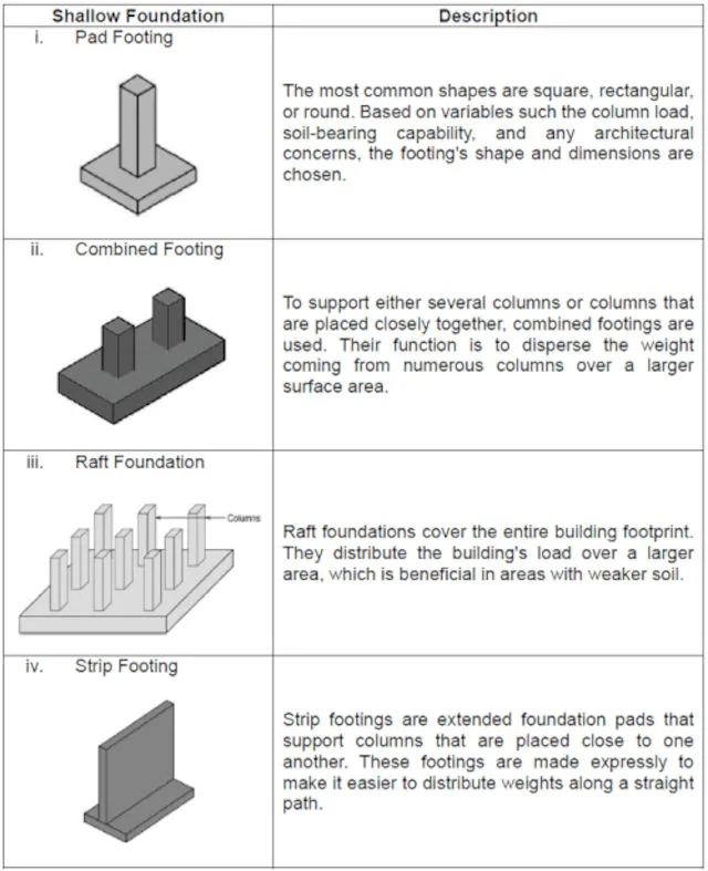
LOAD-BEARING CONSIDERATIONS
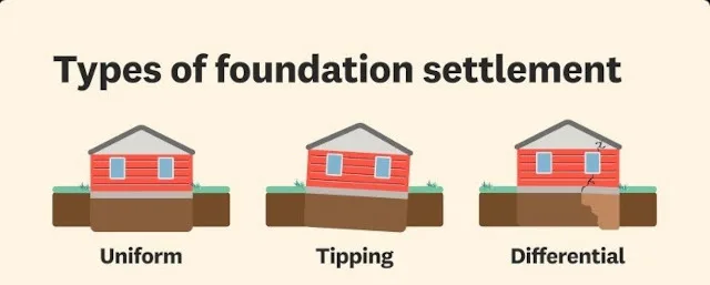
The load-bearing design ensures stability, allowing the foundation to manage differential settlement and efficiently transfer structural loads to the soil.
- Soil Interaction: Our design accounts for soil-structure interaction, ensuring the foundation can handle differential settlement and variations in soil properties.
- Load Transfer: The foundation effectively transfers loads from the structure to the soil, maintaining stability and preventing excessive settlement or movement.
SEISMIC DESIGN
The seismic design prioritizes safety and resilience in California’s earthquake-prone environment.
- Seismic Provisions: Given California’s seismic activity, the foundation design incorporates provisions to withstand earthquake forces, providing ductility, a material’s ability to deform under stress without breaking, and energy dissipation through appropriate detailing and reinforcement.
- Lateral Forces: The foundation resists lateral forces and provides adequate anchorage for the structure.
DURABILITY AND PROTECTION
The foundation is designed with durability in mind, incorporating protections against moisture, chemicals, freeze-thaw cycles, and aggressive soil conditions to ensure long-term stability.
- Exposure Conditions: The concrete foundations are designed to resist environmental exposure conditions such as moisture, chemicals, and freeze-thaw cycles.
- Protective Measures: Adequate measures have been taken to protect the foundation from aggressive soil conditions and potential degradation.
RELEVANCE TO THE ULTIMATE CLASSROOM
For the Ultimate Classroom footer, foundations, and flooring, our adherence to ACI 318 Code ensures a robust and compliant foundation system. Specifically:
FOOTERS AND FOUNDATIONS
The footers and shallow foundations have been designed to distribute loads effectively, considering the soil bearing capacity and ensuring minimal settlement. Proper reinforcement and detailing guarantee structural integrity and longevity.
SEISMIC DESIGN
Given California’s seismic activity, the foundation design incorporates seismic provisions to ensure stability and safety during earthquakes.
MATERIAL SELECTION
High-quality concrete and reinforcement materials have been chosen to meet durability and strength requirements, contributing to the overall sustainability and performance of the structure.
LOAD TRANSFER AND SOIL INTERACTION
Our design accounts for soil structure interaction, ensuring the foundation can handle differential settlement and variation in soil properties, which is crucial for maintaining the stability of the straw bale walls.
By thoroughly reviewing and implementing ACI 318 2019 provisions, the foundation design for the Ultimate Classroom meets the necessary safety, durability, and performance standards, providing a solid base for this innovative and sustainable construction project.
COMPLIANCE STRATEGY
The steps and considerations outlined in this Compliance Strategy ensure that The Ultimate Classroom’s design and construction adhere to all relevant codes and standards. Follow these guidelines as a tutorial and manual for replicating the project.
UNDERSTANDING REGULATORY REQUIREMENTS
Begin by researching and understanding local building codes and regulations. For California, refer to the California Building Code and CALGreen Standards.
Identify key standards relevant to your project, such as seismic design, soil bearing capacity, foundation types, and environmental conditions. Consult with your local engineer to ensure all regulations are met.
CONDUCTION PRELIMINARY ASSESSMENTS
 Perform a thorough site analysis to understand geographical and environmental factors. This includes soil type, seismic activity, wind loads, and flood risks. Conduct soil tests to determine the bearing capacity and identify any special considerations such as the presence of expansive soils.
DESIGNING TO CODE
Incorporate seismic provisions from ACI 318 and CBC into your design. Ensure ductility, adequate reinforcement, and energy dissipation. Design footings and foundations according to ACI 318-2019 standards or any latest edition at the time.
Verify that they are sized correctly and reinforced to handle expected loads and soil conditions. Choose materials that comply with code requirements and are suitable for the specific environmental conditions of the site.
DESIGN CRITERIA
Designing the Ultimate Classroom involves ensuring structural integrity, durability, and sustainability while complying with ACI 318 standards and California Building Codes.
Start with the footings, ensuring they resist both one-way and two-way shear forces and meet flexural requirements. Perform necessary calculations to confirm the footings can handle vertical loads and prevent shear and bending failures.
For the Foundation, ensure it distributes loads effectively to the soil without exceeding its bearing capacity.
Conduct soil tests and load distribution calculations to prevent excessive settlement. Consider soil-structure interaction to mitigate potential settlement issues and include seismic design to withstand earthquake forces. Geotechnical report and interpretation coming later.


VIDEO COMING: ON-SITE SOIL TESTING
SEE OUR HOW TO HELP AND/OR CROWDFUNDING CAMPAIGN PAGE TO HELP CREATE ALL THE TUTORIAL VIDEOS FASTER
When designing the flooring, choose durable and energy-efficient materials. For the Ultimate Classroom, we have used a concrete slab paired with Rockwool insulation for thermal and acoustic benefits. Prepare the surface properly, install Rockwool insulation, and include a moisture barrier. Use various finishing techniques for the concrete and ensure proper curing.
These design criteria have allowed the Ultimate Classroom to meet regulatory standards, support sustainability, and provide a safe and effective learning environment.
LOADS FOR THE ULTIMATE CLASSROOM FOOTER, FOUNDATION, AND FLOORING
This section provides a summary of the load and structural calculations for the Ultimate Classroom’s foundation and footer, developed using STAAD.Pro. The calculations incorporate key load assumptions, including dead loads and long-term live loads from permanent building materials, along with live loads associated with occupant movement, and roof loads for snow and wind resistance.
The design specifies footer dimensions based on these loads, with typical footings measuring 3.333 ft x 1.500 ft x 0.667 ft, sized to support the structural requirements and load distribution safely. Reinforcement design includes #3 reinforcement steel bars spaced at 11.000 inches on center (o.c.), with reinforcement checks meeting criteria for both flexure and shear in accordance with ACI 318 standards. For complete calculations and analysis, refer to the Foundation Calculation Report.
WIND LOAD & WIND ANALYSIS
In Structural Design, the pressure exerted by the wind is among the most critical factors to consider. Proper wind load analysis is essential to ensure that buildings can withstand potential wind forces, thereby safeguarding the structural integrity and safety of the occupants.
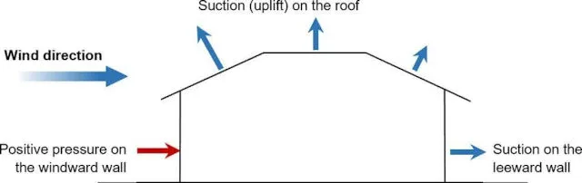
For the Ultimate Classroom project, wind load calculations follow the ASCE 7 – 16 standards, applicable California codes, and specific project parameters i.e.
Basic Wind Speed: Vult = 130 mph
Vasd = 101 mph, Design is based on Allowable Stress Design where:
- Vult (Ultimate Design Wind Speed): According to the ASCE 7-16, this represents the 3-second gust wind speed at 33 feet, 10 meters, above the ground in Exposure C, derived from wind hazard maps. It is used in strength-based design to calculate wind pressures with safety factors already included.
- Vasd (Allowable Stress Design Wind Speed): According to the ASCE 7-16, this represents the equivalent wind speed for allowable stress design (ASD). Vasd is derived by dividing Vult by a factor of 1.6 to adjust for service-level loads without safety factors.
- Importance Factor: Iw = 1.0
- Wind Exposure: C
- Internal Pressure Coefficient, see as elaborated in sections below.
VELOCITY PRESSURE CALCULATION
The first step in wind load analysis is determining the velocity pressure (Qz). This depends on wind speed and topographic location and equals a multiplication of 0.00256 lb/ft2 times the velocity pressure exposure coefficient (Kz), Topographic Factor (Kzt), Wind directionality factor (Kd), and Basic Wind Speed squared (V2):
Qz = 0.00256 Kz Kzt Kd V2 [lb/ft2]
Where :
Kz: Velocity pressure exposure coefficient
Kzt: Topographic Factor
Kd: Wind directionality factor
V: Basic Wind Speed
For our project:
- Basic wind speeds: Vasd = 101 mph, Vult = 130 mph
- Exposure Category: C
- Importance Factor: 1.0
Using the ASCE 7 – 16 Table 27.3-1, the velocity pressure exposure coefficient Kz can be calculated as:
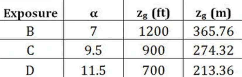
Kz = 2.01 (z/zg)2/α
Where :
- z is the height above the ground and should not be less than 15 feet 4.5 meters, except that z shall not be less than 30 feet 9 meters, for exposure B for low-rise buildings and for components and cladding.
- α is the exponent representing the terrain’s effect on the wind speed profile.
- zg is the gradient height for the specific terrain category.
The parameters are taken as follows:
Kzt = (1 + K1K2K3)2
Given that the site conditions don’t significantly impact the topographic factor, we assume Kzt = 1.0.
DESIGN WIND PRESSURE OR MWFRS
For the Main Wind Force Resisting System (MWFRS), we calculate the design wind pressure using:
PMWFRS = qGCp – qi(GCpi)
Where :
- q: Velocity pressure at height z
- qi: Internal pressure; its evaluation is shown below
- G: Gust response factor, 0.85
- Cp: External pressure coefficient
- GCpi: Internal Pressure Coefficient from ASCE 7-16 Table 26.11-1
It is important to note that the variable qi is evaluated differently for enclosed and partially enclosed buildings, i.e.
Enclosed Building: qi = qh evaluated at mean roof height for windward, leeward, and sidewalls, and roof.
Partially Enclosed Building: qi = qh for negative internal pressure and qi = qz for positive internal pressure at height z at the level of highest opening.
For our structure, a rigid building with a gable roof, the external pressure coefficients Cp and internal pressure coefficients GCpi are derived from the ASCE 7 – 16 Figure 27.4-1.
WIND PRESSURE ON COMPONENTS AND CLADDING (C&C)
For components and cladding, the wind pressure is determined using:
P = qh(GCp) – qi(GCpi)
Where :
- qh: Velocity pressure at mean roof height h.
- GCp: External pressure coefficient for the specific building elements.
PARAPETS AND ADDITIONAL CONSIDERATIONS
The impact of parapets on wind loads is calculated as:
Pp = qp(GCpn)
Where :
- GCpn is the combined net pressure coefficient.
SUMMARY
Wind load analysis is crucial for ensuring the structural safety and integrity of the Ultimate Classroom. Following the ASCE 7 – 16 standards and California codes, we calculate velocity pressure, design wind pressures for the Main Wind Force Resisting System (MWFRS), and wind pressures on components and cladding.
It is worth noting that standards and codes like the ASCE 7-16 are regularly updated and it is key to do relevant research & consulting depending on your area, when looking to replicate wind load analysis for your Ultimate Classroom.
This comprehensive approach ensures the structure can withstand extreme wind conditions. The methodology includes both a simple procedure for quick estimates and an analytical procedure for more precise calculations, providing clear guidance for the wind analysis and design considerations.
MATERIAL PROPERTIES
Selecting the right materials and understanding their properties is crucial for the structural performance of The Ultimate Classroom. Use high-quality concrete with the necessary compressive strength, typically specified in psi, ensuring it meets the durability requirements for the foundation and flooring.
Steel reinforcement bars with adequate yield strength should be chosen to handle tensile forces, with proper spacing and placement according to design specifications. Properly compacted and dried straw bales with consistent density are essential for walls, meeting both thermal and structural requirements.
Rockwool has been chosen for insulation because of its excellent thermal and acoustic properties, and it must be installed correctly to maintain its insulating performance. Additional materials such as geotextile fabric, gravel for footings, and moisture barriers should also meet the project’s specifications and performance requirements.
FOUNDATION DESIGN
Designing the foundation for The Ultimate Classroom is a critical step that ensures the stability, durability, and compliance of your structure. Let’s explore steps on how to achieve this step-by-step:
EXCAVATION AND PREPARATION
Begin by excavating the site to the required depth, accounting for the local frost line to prevent frost heave. The additional 24” by 12” trench to be excavated around the perimeter is for the footer. Consult OHSA’s Trench and Excavation Safety guidelines and your local engineer to verify trench stability. Depending on the soil type, the trench may need to be wider than 24” and may require additional support. This excavation must be wide enough to accommodate the foundation and any additional components like drainage systems. This meticulous preparation is crucial for the foundation’s stability.
VIDEO COMING: EXCAVATION KEY LEARNINGS AND SUGGESTIONS
SEE OUR HOW TO HELP AND/OR CROWDFUNDING CAMPAIGN PAGE TO HELP CREATE ALL THE TUTORIAL VIDEOS FASTER
VIDEO COMING: EXCAVATION TIMELAPSE
SEE OUR HOW TO HELP AND/OR CROWDFUNDING CAMPAIGN PAGE TO HELP CREATE ALL THE TUTORIAL VIDEOS FASTER
FOOTINGS
Design the footings to manage one-way and two-way shear forces and flexural requirements. Calculate the design shear strength of the concrete to handle vertical loads from the straw bale walls without shear failure.
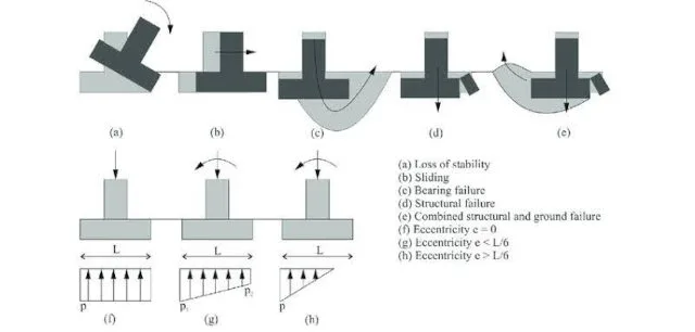 Typical Excavation Detail – Click to Enlarge
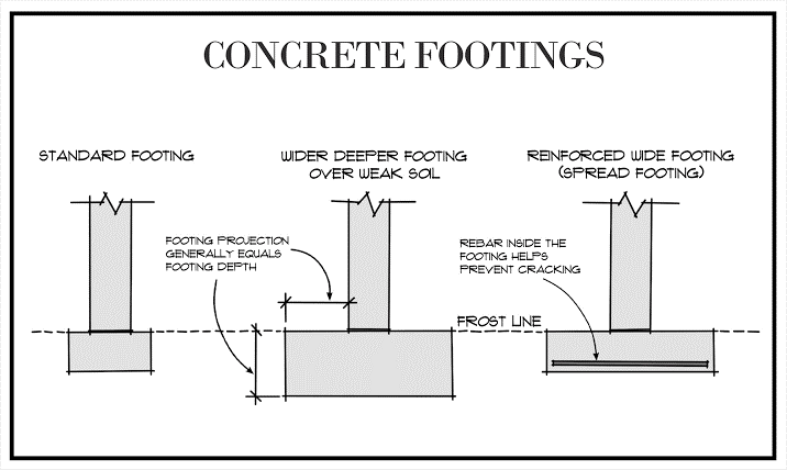
Perform calculations to verify that the footings can resist these forces, preventing punching failure around the structural elements. Reinforce the footings with steel bars to enhance their strength and stability. Proper rebar placement is essential for structural integrity. Place the footings below the frostline to prevent movement during freeze-thaw cycles. The footer will consist of compacted gravel and geotextile fabric, allowing for water drainage.
Depending on the soil classification of the site, a drainage tile may be necessary. Detailed instructions for the footer are discussed in a later section.
REINFORCEMENT
Use steel reinforcement bars, rebars, within the foundation to handle tensile stresses. Ensure the bar is placed according to the design specifications for adequate reinforcement. Spacing and placement are very important and crucial to prevent bending-related failures.
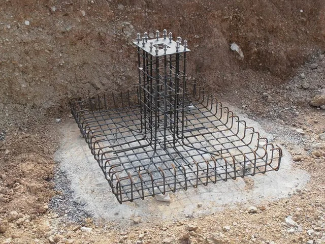
Reinforce the concrete footings and foundations to ensure they can support the applied loads. This reinforcement is essential for maintaining the foundation’s structural integrity over time.
CONCRETE POURING
Pour the required grade and quality of concrete into the foundation forms, ensuring it is properly mixed and placed to avoid air pockets and ensure uniform strength. Use vibrators to consolidate the concrete and remove any trapped air. Proper curing of the concrete is essential to achieve the desired strength and durability. Allow the concrete to cure according to the manufacturer’s recommendations to ensure it reaches its full strength. This step is vital for the foundation’s longevity and stability.
SEISMIC CONSIDERATION
In California, seismic design is crucial. It is key for any builder to ensure the foundation has features that enhance ductility, not rigidity, and energy dissipation to withstand earthquake forces. Use seismic load calculations to determine the necessary reinforcements and design details. Seismic design is essential for the structure’s safety in earthquake-prone areas.
DRAINAGE AND WATERPROOFING
Install a drainage system around the foundation to prevent water accumulation, which can weaken the structure.
VIDEO COMING: DRAINAGE AND WATERPROOFING INSTALLATION….
SEE OUR HOW TO HELP AND/OR CROWDFUNDING CAMPAIGN PAGE TO HELP CREATE ALL THE TUTORIAL VIDEOS FASTER
Regardless if a drainage tile is required in the footer, the bottom of the footer will need to be sloped 1-2% for exterior drainage, the outer part of this footer trench will be a little deeper than the inner part.
This will aid in preventing water from ponding underneath the classroom, and potentially damaging the footer, foundation and flooring systems. With a 2’ wide footer, the outer bottom edge of the footer will be roughly 0.5” lower than the inner bottom edge, assuming a 2% drainage slope. Use waterproofing membranes or coatings to protect the foundation from moisture penetration, ensuring long term durability. Proper drainage and waterproofing are critical to maintaining the foundation’s integrity over time.
FOOTERS
The ACI 318 Building Code Requirements for Structural Concrete provides detailed guidelines for designing footings to ensure they safely and effectively support structural loads. Here, we focus on the design criteria for footings, specifically addressing one-way and two-way shear, flexural requirements, and the related calculations. These principles have been applied in designing the foundation for The Ultimate Classroom project.
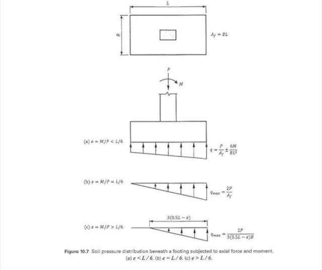 Typical Structural Footing Design Detail – Click to Enlarge
ONE-WAY SHEAR
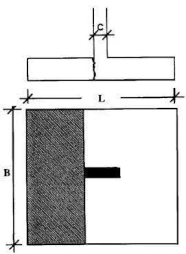
One-way shear, or beam shear, occurs along a plane perpendicular to the direction of the applied load. It is critical in footings where the load is transferred from columns or walls.
DESIGN CRITERIA
The footing must be designed to resist one-way shear forces. According to ACI 318, the critical section for one-way shear is located at a distance d, effective depth of the footing, from the face of the column or wall.
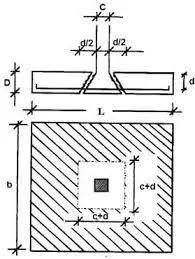
CALCULATIONS
The design shear strength, Vc, of the concrete is calculated based on the footing’s width, depth, and the concrete’s compressive strength. The applied shear force, Vu, should not exceed Vc.
APPLICATION
In the Ultimate Classroom project, one-way shear calculations ensure that the footings can handle the vertical loads transferred from the straw bale walls without failing in shear.
TWO-WAY SHEAR (PUNCHING SHEAR)
Two-way shear, or punching shear, occurs around the perimeter of a column or concentrated load, causing a potential punching failure through the footing.
DESIGN CRITERIA
The footing must be designed to resist two-way shear forces. The critical section for two-way shear is located at a distance d/2 from the perimeter of the column or concentrated load.
CALCULATIONS
The design shear strength, Vc, is calculated considering the concrete’s compressive strength and the perimeter of the critical section. The applied punching shear force, Vu, should not exceed Vc.
APPLICATION
For the Ultimate Classroom, two-way shear calculations ensure that the footings can withstand the concentrated loads from structural elements without punching through.
FLEXURAL REQUIREMENTS
Flexural strength, or bending strength, refers to the ability of the footing to resist bending moments induced by the applied loads.
DESIGN CRITERIA
Footings must be designed to resist bending moments. Reinforcement is required to handle tensile stresses resulting from bending.
CALCULATIONS
The flexural design involves determining the required area of reinforcement, steel bars, based on the bending moment, footing dimensions, and material properties. The design moment capacity, Mn, should exceed the applied moment, Mu.
APPLICATION
In the Ultimate Classroom project, flexural calculations ensure that the footings have sufficient reinforcement to resist bending moments, preventing cracking and structural failure.
SHEAR CALCULATIONS
- One-way shear is obtained by multiplying the load applied per unit area, ω, and the span, L, and accounting for only one direction by dividing the product by 2.
Vu = ωL 2
- For two-way shear for concentrated load, it is obtained by multiplying the load per unit area and the square of the span, L2. Divide the product by 4 to account for shear in all directions.
Vu = ωL2 4
- Compare Vu with Vc to ensure safety.
FLEXURAL CALCULATIONS
- Maximum bending moment for a beam structure subjected to uniformly distributed loads is determined using a standard formula that considers the load intensity and the span length of that beam structure.
Mu = ωL2 ÷ 8
- To determine the required reinforcement area for a beam, the calculation considers the bending moment, material properties, and beam geometry. The formula used is:
As = Mu ÷ [φfy(d – a2)]
Where:
- As = Required reinforcement area, mm2
- Mu = Maximum bending moment, kNm
- φ = Strength reduction factor
- fy = Yield strength of steel, MPa
- d = Effective depth of the beam, mm
- a2= Depth of the equivalent rectangular stress block, mm
In designing the foundation for The Ultimate Classroom, we adhered to these criteria and performed the necessary calculations to ensure the footings can resist shear and flexural forces. This ensures the foundation system is robust, durable, and compliant with ACI 318 standards, providing a solid base for this innovative and sustainable construction project.
FOUNDATION TYPES
Choosing the right foundation for The Ultimate Classroom is pivotal, and with thorough research and consideration of ACI 318 standards along with relevant California codes, we have crafted a robust replicable foundation design.
COMMON FOUNDATION TYPES
Foundation systems are generally classified into shallow and deep foundations based on soil conditions and structural load requirements.
- SHALLOW FOUNDATIONS: Including spread footings, strip footings, and mat, or raft, foundations, these are ideal when the soil has adequate bearing capacity near the surface. They are straightforward to construct and cost-effective, making them a popular choice for many projects.
- DEEP FOUNDATIONS: Comprising piles and drilled shafts, or caissons, these are essential when surface soils cannot support the structure’s load, necessitating transfer to deeper, stable soil layers or bedrock. While more complex and expensive, deep foundations provide the necessary support in challenging soil conditions.
SELECTED FOUNDATION TYPE
For the Ultimate Classroom, after evaluating the soil conditions and the light load of straw bale construction, a shallow foundation has been chosen. We are combining spread footings and a slab-on-grade foundation to ensure stability and durability.
SPREAD FOOTINGS
- Spread footings are crucial for supporting the wall and any concentrated loads.
- As per ACI 318-2019, spread footings distribute the structure’s load over a larger area, reducing soil pressure. This design minimizes settlement and gives structural strength.
- Reinforcement is calculated to handle bending moments and shear forces, with a keen focus on one-way and two-way shear, along with the flexural requirements.
- These footings are placed below the frostline to prevent movement during freeze-thaw cycles, ensuring long-term stability.
SLAB-ON-GRADE FOUNDATION
- The slab-on-grade foundation provides a continuous, solid base for the floor, ideal for the lightweight straw bale construction.
- This type of foundation is exceptional in seismic zones like California, offering resistance to lateral forces.
- In compliance with ACI 319-2019 and the California Building Code, the slab’s thickness, reinforcement, and concrete strength are designed to handle all imposed loads and environmental conditions.
- The slab includes a layer of compacted gravel and a vapor barrier to prevent moisture penetration. For enhanced thermal performance, we’ve integrated Rockwool Insulation.
- Rockwool, also known as mineral wool insulation, is a type of insulation made from natural rock materials, such as basalt and diabase, and recycled slag. These materials are melted and spun into fibers, which are then compressed to create a dense, heat-resistant, and sound-absorbing material.
REGULATORY COMPLIANCE
In summary, for the design:
- Meeting ACI 318-2019 standards involves precise calculations for load-bearing capacity, shear strength, and flexural strength.
- Adhering to the California Building Code (CBC) requirements, especially regarding seismic design, we ensure proper reinforcement detailing and the use of ductile materials to absorb and dissipate energy during earthquakes.
- Drainage systems around the foundation are meticulously designed to prevent water accumulation, aligning with both the ACI 318 and CBC guidelines for moisture control and foundation durability.
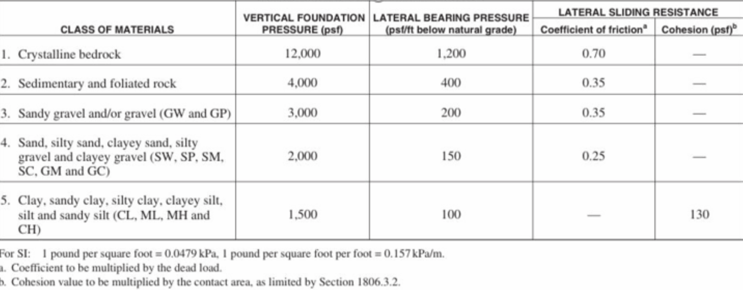 FOUNDATION DESIGN GUIDELINES Click to Enlarge
By following these carefully researched and detailed guidelines, you can be able to replicate a foundation for The Ultimate Classroom that is safe, durable, and code-compliant. This ensures your structure will withstand local environmental conditions and support sustainable practices.
DESIGN CALCULATIONS
This section presents the detailed design calculations for the foundation of The Ultimate Classroom, ensuring compliance with ACI 318 and CBC. The calculations ensure the foundation can adequately support the loads imposed by the structure.
BEARING CAPACITY
The bearing capacity of the soil is a critical factor in determining the foundation’s ability to support the structure.
Ultimate Bearing Capacity, Qu, is calculated using the following formula:
Qu = cNc + σ’Nq + 0.5γBNγ
Where:
- c = soil cohesion
- σ’ = effective stress due to surcharge
- γ = unit weight of soil
- B = footing width
- Nc, Nq, Nγ = bearing capacity factors based on the soil type and footing shape
Allowable Bearing Capacity (Qa) :
Qa = Qu / FS
Where FS is the factor of safety (typically 3).
FOOTING SIZE
To determine the footing size, use the load from the structure and allowable bearing capacity:
- Footing Area (A):
A = P / Qa
Where P is the load from the structure.
- Footing Dimensions:
For a square footing:
B = √A
The finalized dimensions for the Ultimate Classroom based on the governing load case are:
Length, L2 = 3.333 ft
Width, W2 = 1.500 ft
Depth, D2 = 0.667 ft
Area, A2 = 5.000 ft2
SHEAR AND FLEXURAL REQUIREMENTS
Ensuring the footing can resist shear forces and bending moments is essential for a stable foundation.
- One-way Shear:
Vu = qB (d/2)
where Vu = shear force
q = pressure on the footing
B = footing width
d = effective depth
- Shear Strength (Vc):
Vc = 0.75 * min ( Vc1, Vc2, Vc3 )
where Vc1, Vc2, Vc3 are calculated based on different factors as per ACI 318.
For our project: Vc1 = 43.450 kip
Vc2 = 60.469 kip
Vc3 = 50.829 kip
Vc = 0.75 × min(Vc1, Vc2, Vc3) = 32.588 kip
- Punching Shear:
Vu ≤ 0.75Vc
FLEXURAL REQUIREMENTS
- Moment, M:
M = qB2 ( l/8 )
where l is the footing length.
- Steel Reinforcement Area, As:
As = M / ( Φ * fy * d )
where:
Φ = strength reduction factor
fy = yield strength of steel
d = effective depth
REINFORCEMENT DETAILS
The reinforcement for the footing is designed to handle bending moments and shear forces.
- Longitudinal Reinforcement:
As = M / ( Φ fy )
- Transverse Reinforcement: Transverse bars are placed to resist shear forces and provide additional structural integrity, ensuring the footing remains stable under various loads.
These calculations ensure that the footer and foundation plan for the Ultimate Classroom meets all necessary structural requirements and regulatory standards, providing a safe and stable base for the sustainable classroom.
FLOORING DESIGN
The flooring design for The Ultimate Classroom is critical to ensuring durability, energy efficiency, and indoor air quality. We have selected a concrete slab as the finished flooring due to its durability, cost-effectiveness, and ability to reduce allergens. Additionally, Rockwool insulation will be used for the floor to enhance thermal performance and energy efficiency. Click here for our “Best and Most Sustainable Insulation: Safe, Eco-friendly, LEED Compliant, High R-Value” research.
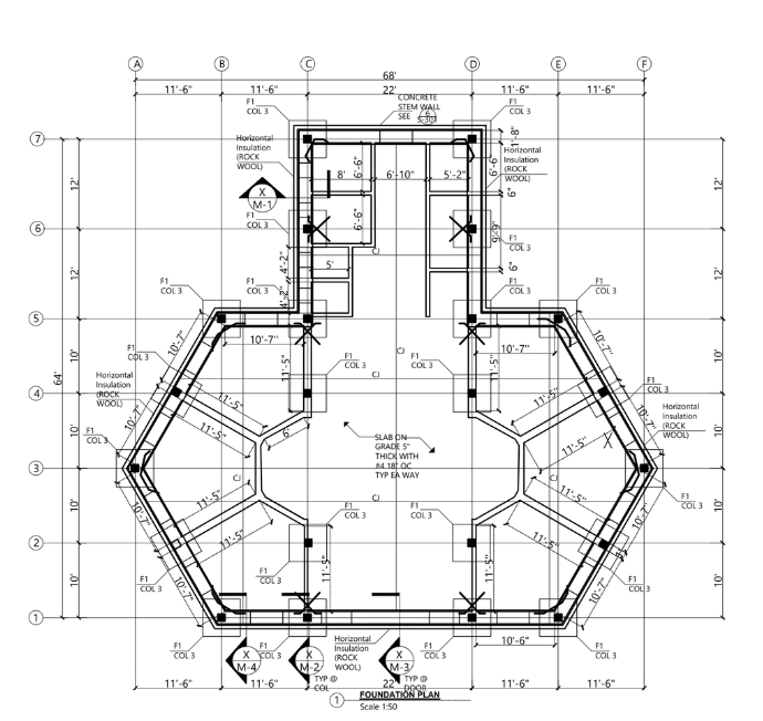
The image shown below gives an outline of Ultimate Classroom’s Foundation Layout including dimensions and positions of the footers and their respective column stubs, insulation and other key information that form the Ultimate Classroom Footer, Foundation and Flooring Design.
MATERIAL SELECTION
For the Ultimate Classroom, we have chosen slab-on-grade polished concrete as the finished flooring type. This decision is based on most sustainable flooring materials research and the need for a durable, low maintenance, and energy-efficient flooring solution that can handle the demands of a multi-functional learning space. A concrete slab provides excellent thermal mass, contributing to the energy efficiency of the building while offering a strong, stable surface ideal for heavy foot traffic, educational activities, and other uses within the space.
FINISHED FLOORING TYPE: CONCRETE ON SLAB/SLAB-ON-GRADE
This choice aligns with our project goals of sustainability, durability, and cost-effectiveness. Concrete offers a durable surface that requires minimal maintenance and provides a versatile aesthetic option. Below is an image of a typical slab-on-grade in the final stages of curing and finishing.
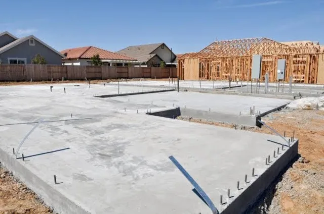
Concrete Slab on Grade Foundation
CONSIDERED FACTORS:
The following factors were considered when selecting the finished concrete floor for the Ultimate Classroom.
- DURABILITY: Concrete is highly durable, making it ideal for high-traffic areas like classrooms. It can withstand heavy use without significant wear and tear.
- ALLERGEN REDUCTION: Unlike carpets, which can trap dust, mold, and other allergens, concrete floors are easy to clean and do not harbor allergens, contributing to a healthier indoor environment.
- COST-EFFECTIVENESS: Using the existing concrete slab as the finished floor eliminates the need for additional flooring material, reducing overall construction costs.
- AESTHETIC VERSATILITY: Concrete can be finished in various styles, including staining, scoring, and stamping, allowing for creative design options that can enhance the classroom environment.
FLOOR INSULATION
Proper insulation of the concrete slab is crucial, especially in regions with extreme temperatures. Insulating the slab helps maintain a comfortable indoor temperature and improves energy efficiency. For this project, we have selected Rockwool for floor insulation. This is based on our most sustainable insulation research and its superior sustainability, thermal and acoustic properties.
THERMAL INSULATION:
Rockwool insulation effectively prevents heat loss during winter and keeps the space cooler in summer, reducing heating and cooling costs. It has a high R-value, which measures its resistance to heat flow.
MOISTURE BARRIER:
Adding a moisture barrier beneath the insulation layer protects the concrete from the ground moisture, which can lead to issues like mold growth or slab deterioration. Rockwool is also water-repellent, enhancing the moisture protection of the flooring system.
INSTALLATION METHOD:
Rockwool insulation can be installed beneath the slab before pouring the concrete or as an overlay on existing slabs. Its rigid structure ensures it stays in place and provides consistent thermal performance.
INSTALLATION PROCESS
The installation process for the concrete slab as the finished flooring, incorporating Rockwool insulation, involves several steps to ensure a high-quality and long-lasting floor surface.
SURFACE PREPARATION
Step 1 is to thoroughly clean the existing slab to remove any dirt, grease, or debris. Then fix any cracks or imperfections in the slab using appropriate repair materials.
VIDEO COMING: SURFACE PREPARATION FOR ROCKWELL INSTALLATION
SEE OUR HOW TO HELP AND/OR CROWDFUNDING CAMPAIGN PAGE TO HELP CREATE ALL THE TUTORIAL VIDEOS FASTER
INSTALLING ROCKWOOL INSULATION
Below is a tutorial and learning video for the installation of Rockwool insulation and simple steps to consider during installation.
VIDEO COMING: ROCKWOOL FLOORING-INSULATION INSTALLATION
SEE OUR HOW TO HELP AND/OR CROWDFUNDING CAMPAIGN PAGE TO HELP CREATE ALL THE TUTORIAL VIDEOS FASTER
Placement: Lay Rockwool insulation boards directly onto the prepared surface, ensuring full coverage and eliminating gaps.
Moisture Barrier: Install a moisture barrier on top of the Rockwool insulation to protect against ground moisture.
FINISHING TECHNIQUES
During the finishing stage, there are several steps critical in order to get the best results:
Staining: Apply chemical stains that react with the concrete to create a range of colors and patterns. Staining can be combined with scoring to produce intricate designs.
Scoring: Use circular saws with special blades to cut shallow grooves and shapes into the floor. This technique can create decorative patterns.
Stamping: For a textured finish, stamping involves pressing patterns, such as bricks, tiles, or stone, into the concrete surface while it’s still wet. This method requires skilled labor to achieve a professional finish.
VIDEO COMING: FLOOR FINISHING TECHNIQUES
SEE OUR HOW TO HELP AND/OR CROWDFUNDING CAMPAIGN PAGE TO HELP CREATE ALL THE TUTORIAL VIDEOS FASTER
SEALING AND POLISHING:
Sealing: Apply a high-quality concrete sealer to protect the surface from stains, moisture, and wear. The sealer also enhances the color and appearance of the stained or stamped concrete.
Polishing: Depending on the desired finish, the concrete can be polished to a high gloss for a sleek, modern look or left with a matte finish to reduce glare.
VIDEO COMING: FLOOR SEALING AND POLISHING PROCESS
SEE OUR HOW TO HELP AND/OR CROWDFUNDING CAMPAIGN PAGE TO HELP CREATE ALL THE TUTORIAL VIDEOS FASTER
CURING
Allow the concrete to cure properly, following the recommended curing time to achieve maximum strength and durability.
Below is an image showing the floor slab cast in panels and going through the finishes and curing process to achieve a good quality finished flooring for the structure.
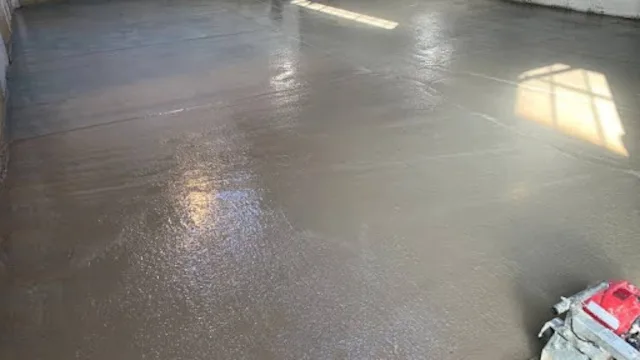
Finishes and Curing Process
These steps can ensure that the concrete flooring of the Ultimate Classroom is not only functional and durable but also aesthetically pleasing and aligned with our sustainability goals. The use of concrete slab as finished flooring and Rockwool insulation contributes to a low maintenance, energy-efficient, and allergen free environment that supports the well-being of the occupants.
The following resource has also been referenced for well detailed information regarding the Use of Concrete Slabs as Finished Flooring. Additionally, we have also explored other options, including Hardwood Flooring for Straw Bale Construction.
AUTOCAD PLANS
The AutoCAD plans include comprehensive drawings of the footer, foundation, and flooring systems adhering to California regulatory standards and the guidelines set forth by ACI 318. These plans serve as a vital tool for builders and engineers, offering a clear and precise visual reference that complements the detailed calculations and specifications discussed in previous sections.
Our AutoCAD plans are meticulously detailed, covering:
- FOOTER DESIGN: Detailed drawings illustrating the footer dimensions, reinforcement details, and placement within the foundation system.
- FOUNDATION LAYOUT: Complete plans for the foundation, showing the layout, reinforcement, and integration with the footer and flooring systems.
- FLOORING SYSTEM: Visual representations of the flooring structure, including material specifications, insulation placement, and reinforcement details.
These plans are designed to be easily understandable and replicable, providing a practical resource for anyone looking to undertake similar sustainable building projects. By following these AutoCAD plans, you can ensure precise construction that aligns with the structural and regulatory requirements detailed in this report.
SECTION VIEW OF THE TYPICAL COLUMN FOOTING
Below is the AutoCAD drawing illustrating a cut section of the column footing for the project. The drawing shows the layout of steel reinforcement at the base of the footing and the connections making up this structural element as a function of the structural design.
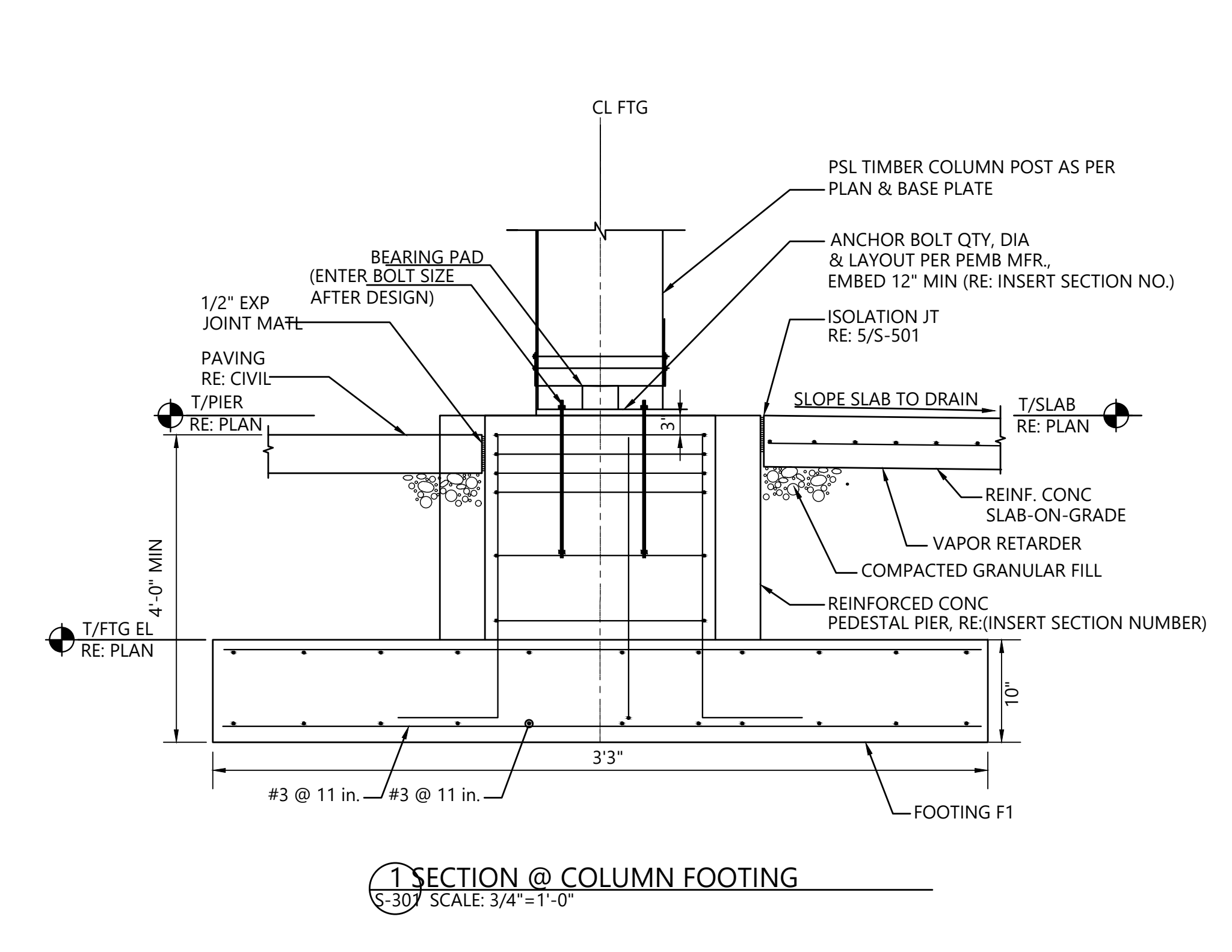 Typical Section View of Column Footing Click to Enlarge
SECTION VIEW AT DOOR OF THE ULTIMATE CLASSROOM
Below is a cross-section of the footing under the door of the Ultimate Classroom. The footing depth is shown, and it is important that the depth accounts for the frost heave, especially at the door.
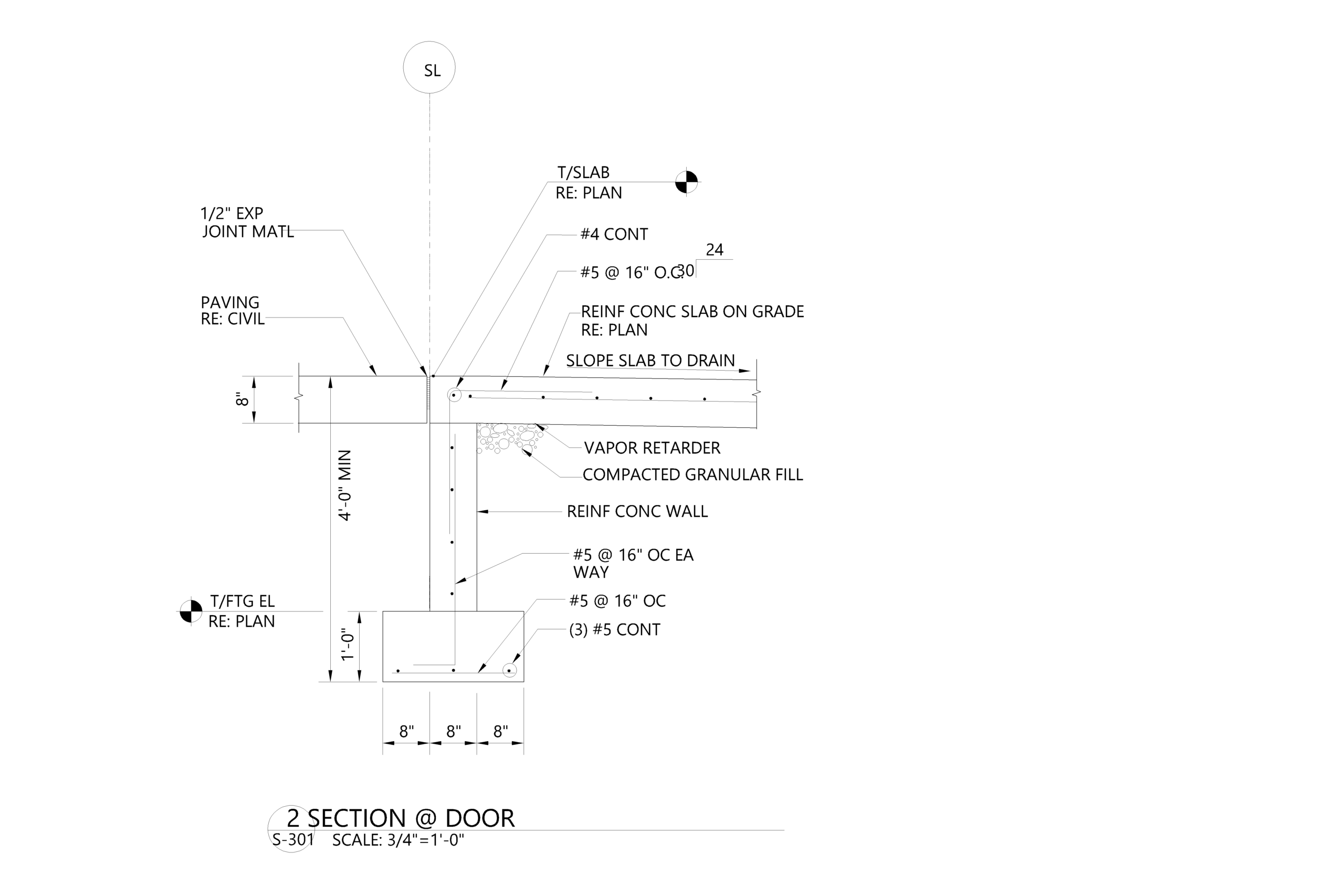 Typical Section View at Door Openings Click to Enlarge
TYPICAL UTILITY PIPE RUNNING THROUGH WALL FOOTING
It is key to always consider utilities and services like drainage pipes etc when detailing and designing footings and slabs. Below is the reinforcement detailing AutoCAD drawings showing a typical utility pipe running through the wall footing.
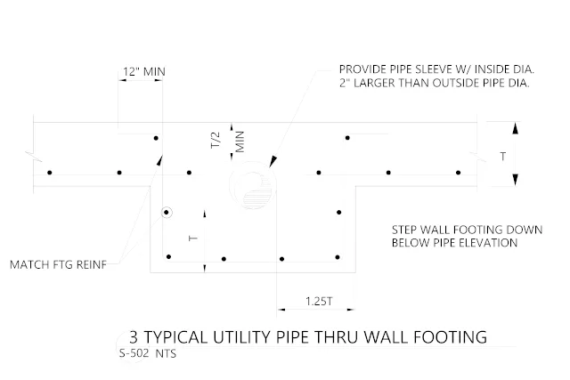 Utility Pipe Through Wall Footing of the Ultimate Classroom Click to Enlarge
Here is the reinforcement detailing AutoCAD drawings showing a typical utility pipe running under the wall footing.
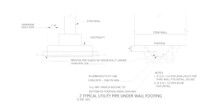 Utility Pipe Placed under Wall Footing of the Ultimate Classroom Click to Enlarge
FOUNDATION PLAN
The foundation plan consists of the different structural elements that make up the Ultimate Classroom Footer, Foundation and Flooring Plan including the typical footings making up the foundation system, the slab-on-grade and the layout of walls and door openings.
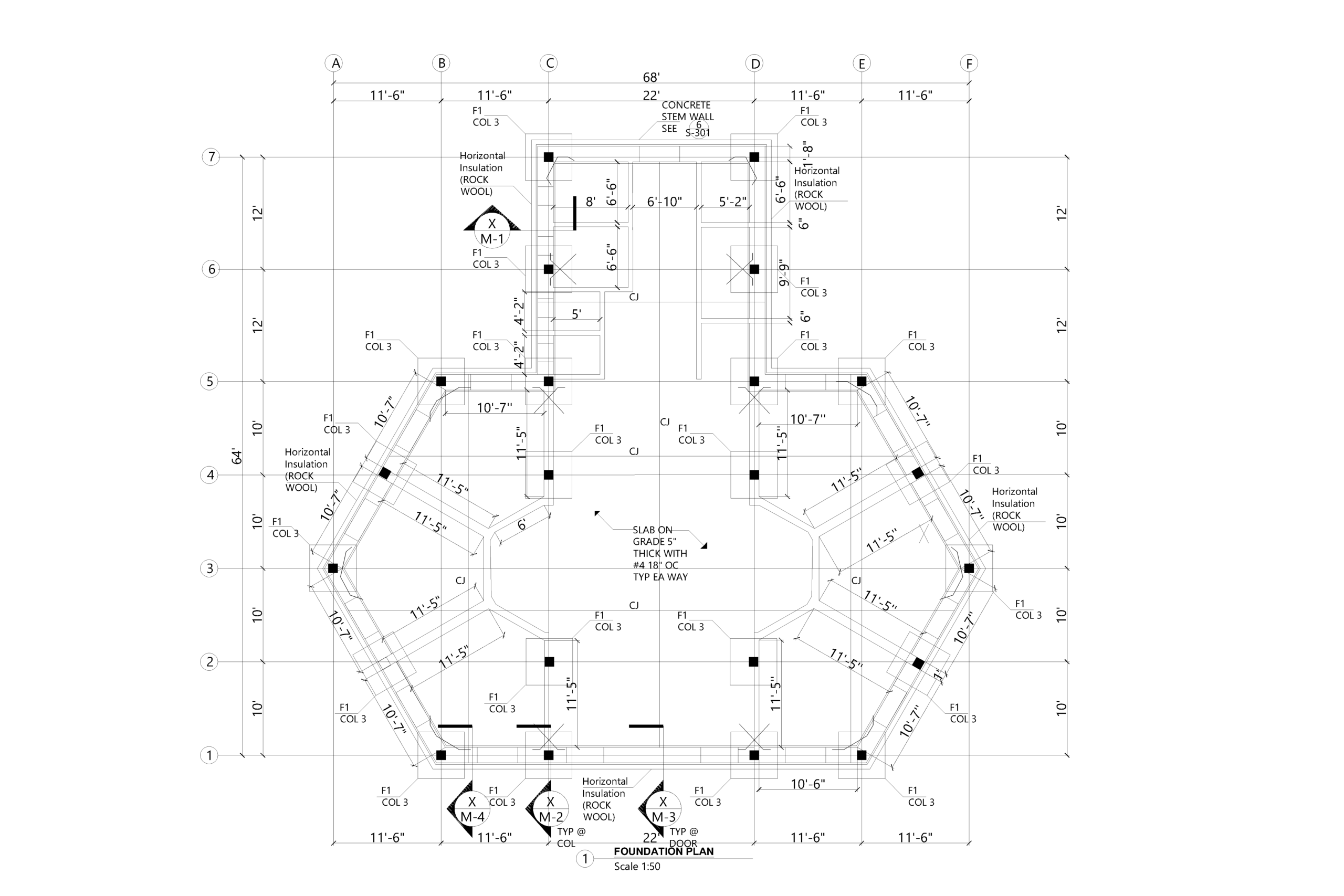 Ultimate Classroom Foundation Layout Click to Enlarge
TYPICAL INTERNAL TRENCH DRAIN
A trench drain has been incorporated as part of the plumbing; however, the reinforcement detailing is as shown below. The drainage system forms a key part of the foundation system.
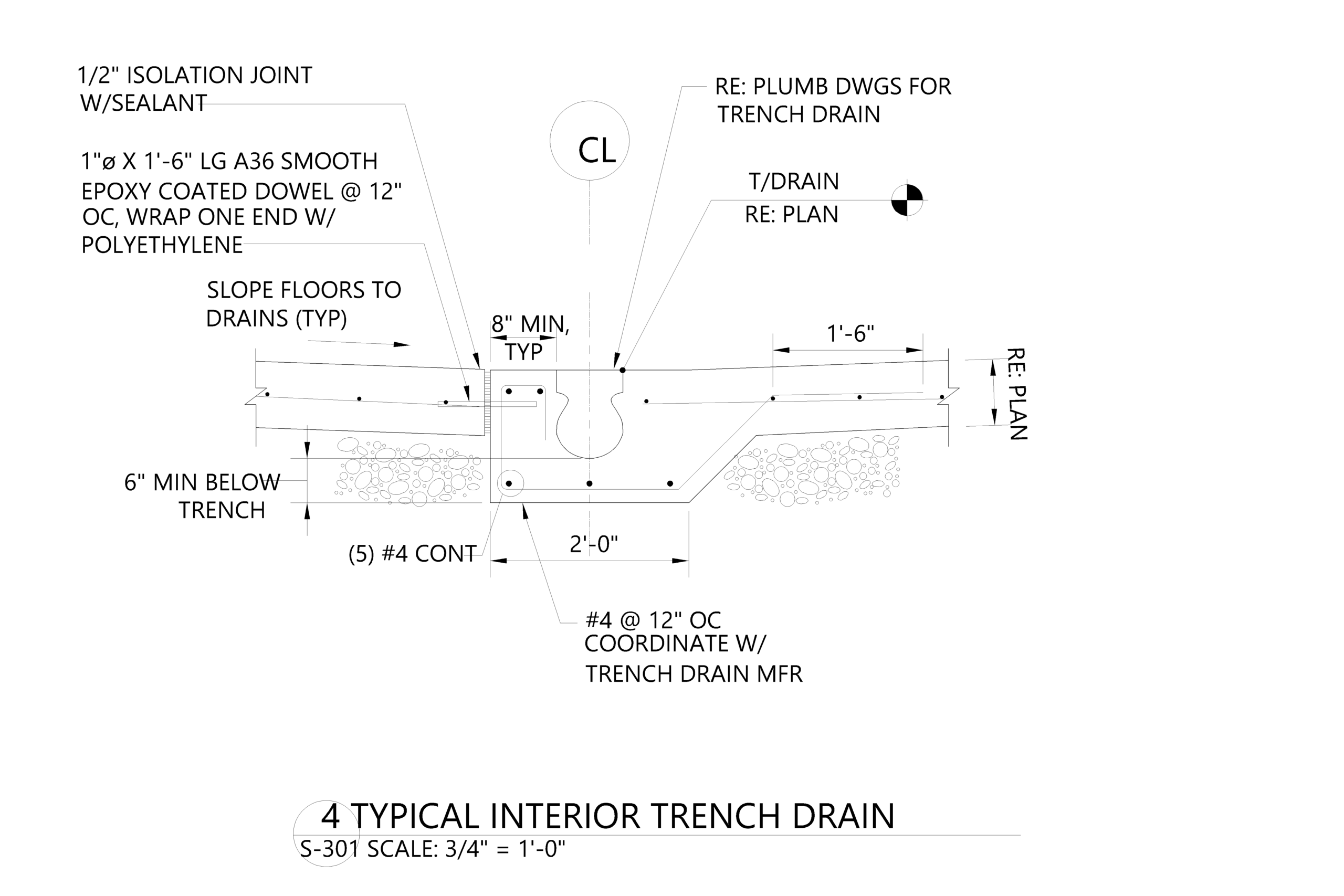 Trench Drain Reinforcement Detail Click to Enlarge
SLAB REINFORCEMENT DETAILING FOR SLAB OPENINGS
Slab openings require careful consideration of reinforcement to avoid cracks in the slab. Below is the reinforcement detailing to be used for proper placing on-site.
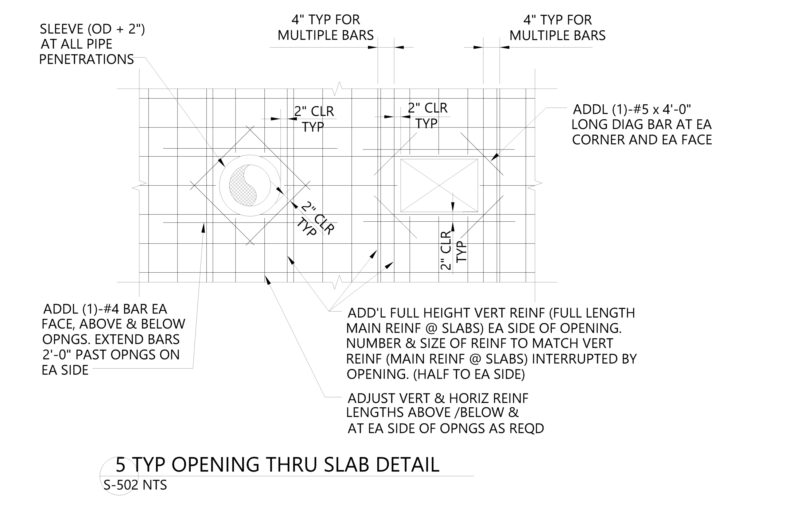 Reinforcement Detail for Slab Openings Click to Enlarge
SLAB ON GRADE JOINTS – CONSTRUCTION & CONTROL JOINTS
It is always key to consider the joints on a slab-on-grade foundation, and adequate reinforcement is required in such joints. Below are the drawings showing reinforcement layout for the construction, control joints, and isolation joints at piers, respectively.
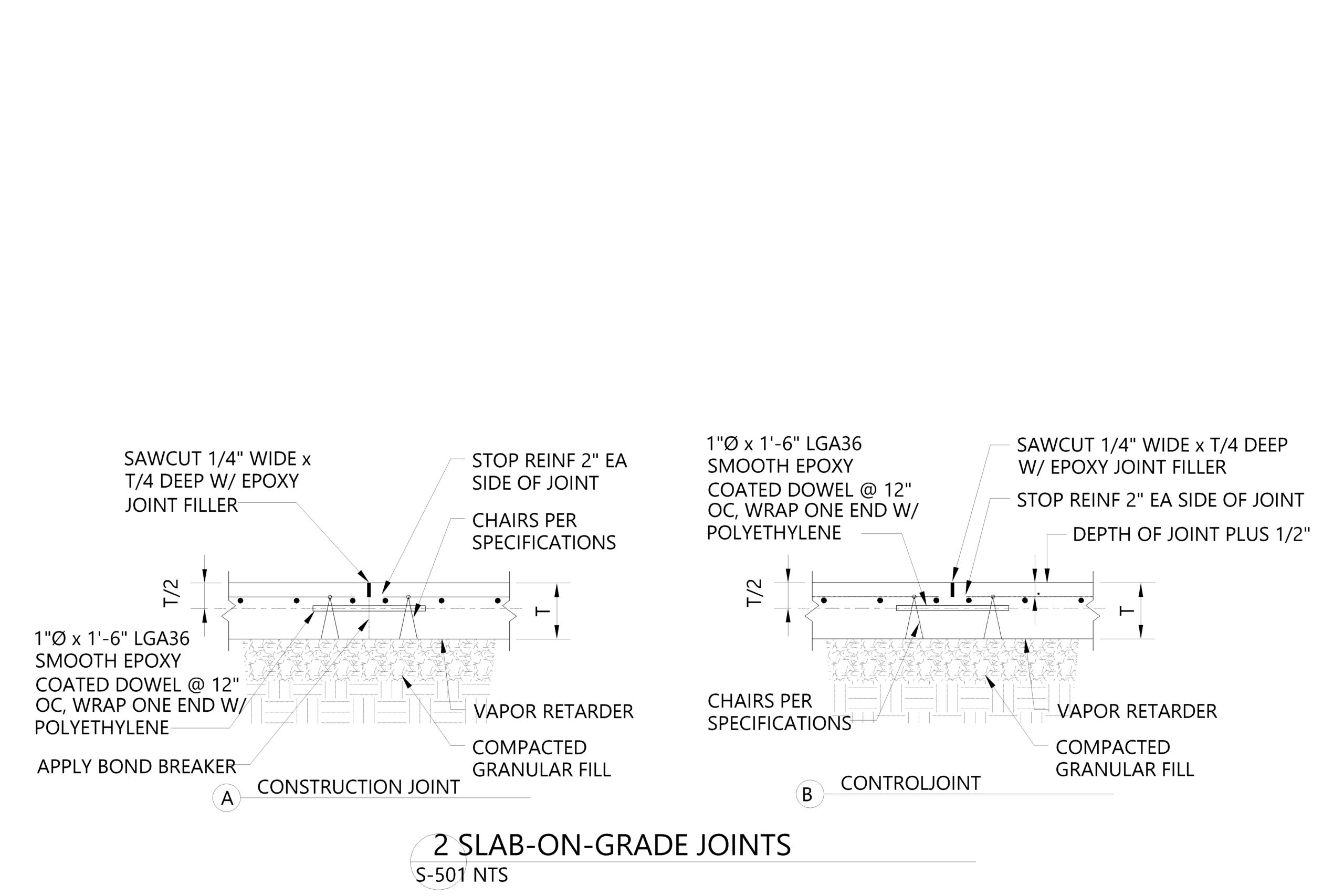 Construction and Control Joints Reinforcement DetailClick to Enlarge
SLAB-ON-GRADE ISOLATION JOINTS
Here is the AutoCAD image showing the typical isolation joints reinforcement.
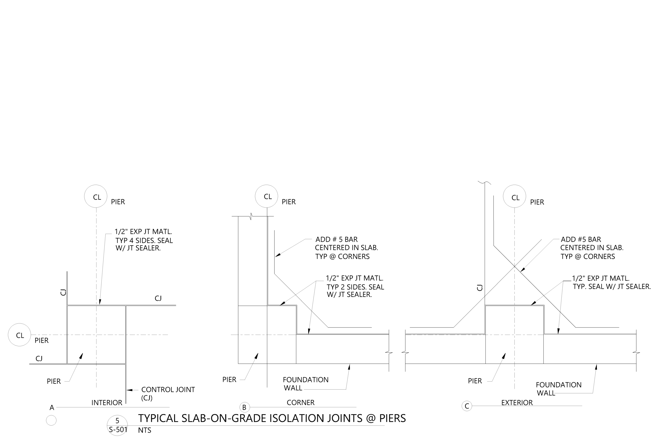 Typical Isolation Joints Reinforcement Detail Click to Enlarge
SECTION: STRAW BALE WALL ON SLAB-ON-GRADE FLOOR
Below is an AutoCAD sectional view showing the structural interaction between the slab-on-grade floor/foundation and the straw bale walls.
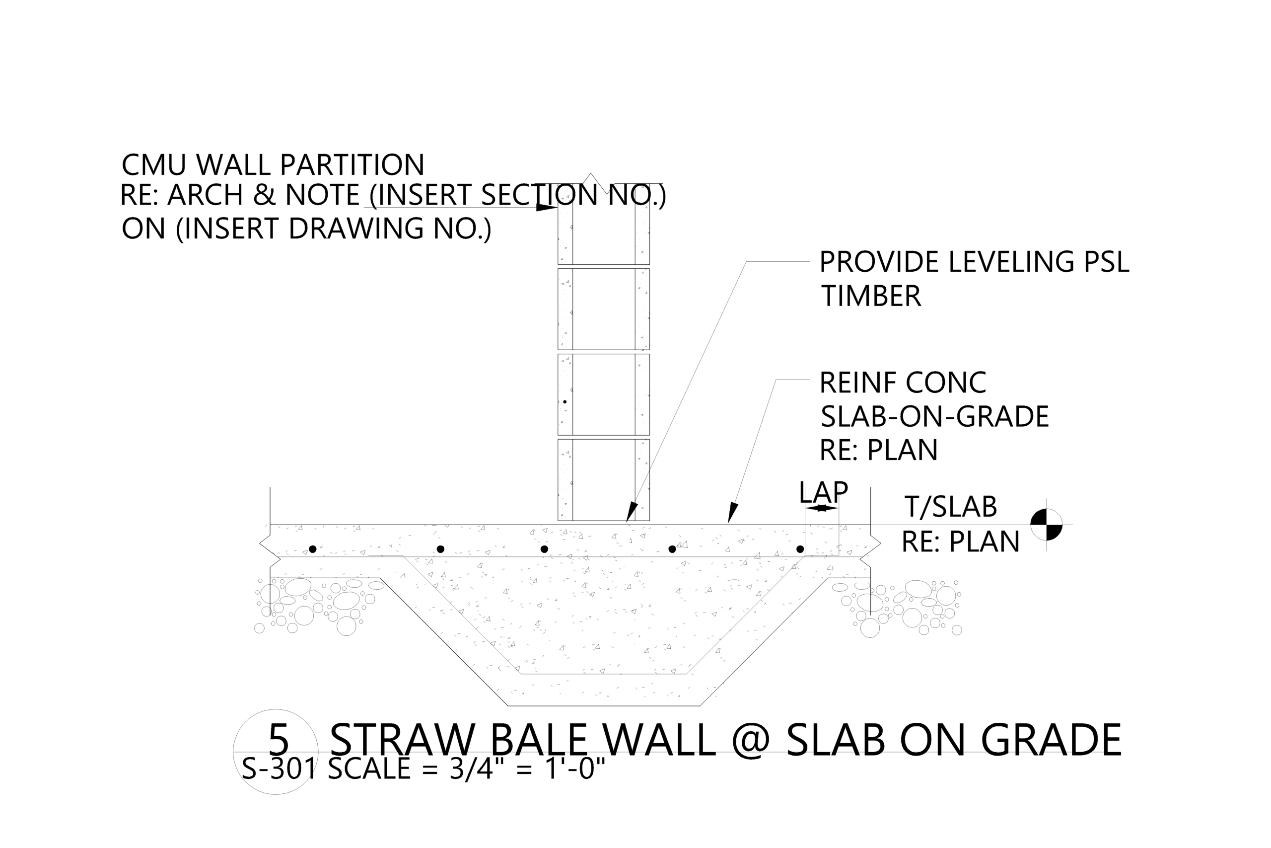 Section of Slab-on-Grade Supporting Straw Bale Wall Above Click to Enlarge
STEP-BY-STEP TUTORIAL & CONSTRUCTION METHODOLOGY
Careful planning and execution are key to constructing a robust and durable foundation and flooring system for the Ultimate Classroom. This section provides a comprehensive guide to the construction methodology, covering every step from excavation to the final flooring installation.
This tutorial is designed to be easily replicable, with clear instructions for each phase of the process.
PURPOSE OF THE ULTIMATE CLASSROOM FOOTER, FOUNDATION AND FLOORING
The Ultimate Classroom is designed to be an all-ages, open-floor, and desk-free learning environment. Its unique layout, featuring a central area large enough to host group circles, social and recreational events, presentations, and more, is enhanced by themed sections that represent all the colors of the rainbow.
Each section is dedicated to specific subjects, providing a stimulating and captivating educational experience that covers traditional subjects and a broad diversity of additional topics. Below, we break down the purpose of each themed section and explain why the Ultimate Classroom’s footer, foundation, and flooring design are crucial to achieving these educational goals.
CONCLUSION
The Ultimate Classroom’s Footer, Foundation, and Flooring design are not just structural necessities; they are integral to creating a safe, supportive, and adaptable educational environment. Each room’s purpose is deeply intertwined with these foundational elements, ensuring that the space can effectively cater to a wide range of educational activities and foster an engaging learning experience for all.
SAFETY MEASURES FOR THE ULTIMATE CLASSROOM CONSTRUCTION SITE

Ensuring the safety of all personnel on the Ultimate Classroom construction site is paramount. Following Occupational Safety and Health Administration (OSHA) guidelines and other relevant safety standards is essential for a safe and successful project. In this section, we cover the critical safety measures specifically for our footer, foundation, and flooring plans.
PERSONAL PROTECTIVE EQUIPMENT
For the Ultimate Classroom construction, appropriate PPE, Personal Protective Equipment, is crucial to safeguard against potential hazards specific to footer, foundation, and flooring work. For appropriate safety, all workers should be equipped with:
- Hard hats: To protect against head injuries from falling objects or debris.
- Steel-Toed Boots: Essential for foot protection from heavy materials and equipment.
- High-Visibility Vests: To ensure all workers are easily seen, particularly important around heavy machinery.
- Gloves: To protect hands from sharp edges, tools, and materials.
- Eye Protection: Safety glasses or goggles to shield eyes from dust, particles, and splashes.
- Hearing Protection: Earplugs or earmuffs to protect against noise from machinery and tools.
- Ensuring that everyone on site is equipped with the right PPE significantly minimizes the risk of injury.
SITE DEMARCATION
Clear demarcation of the construction site is vital. Here’s an example of what that looks like:
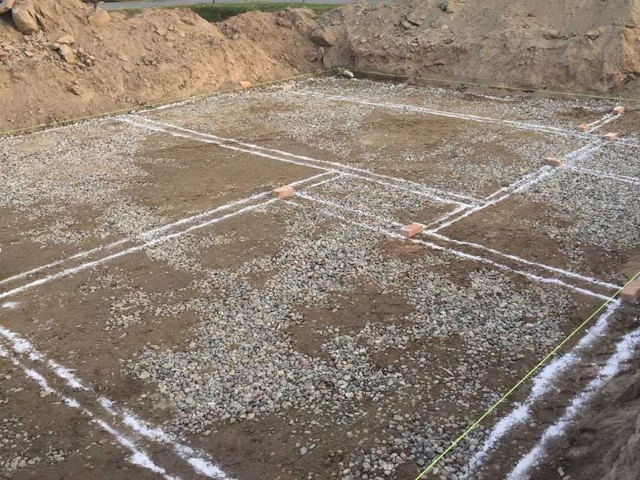
Site Demarcation Image to be replaced with Ultimate Classroom Site Demarcation
Erecting fences and posting warning signs around the perimeter and specific hazardous areas helps prevent unauthorized access and potential accidents. This step is particularly important for protecting workers and visitors from dangers associated with deep excavations and heavy machinery operations.
VIDEO COMING: PROPER CONSTRUCTION-SITE DEMARCATION, FENCING AND SIGNAGE
SEE OUR HOW TO HELP AND/OR CROWDFUNDING CAMPAIGN PAGE TO HELP CREATE ALL THE TUTORIAL VIDEOS FASTER
TRENCH SAFETY
Given the trenching involved for our foundation work, strict safety protocols are necessary: Regular trench inspections should be conducted before work begins. All workers must follow OSHA trench safety guidelines.
Sloping or Benching: Ensure the sides of the trenches are sloped or benched according to OSHA standards to prevent collapses.
Shoring: Utilize shoring systems such as planks or hydraulic jacks to support trench walls.
Shielding: Employ trench boxes or other protective systems to shield workers from cave-ins.
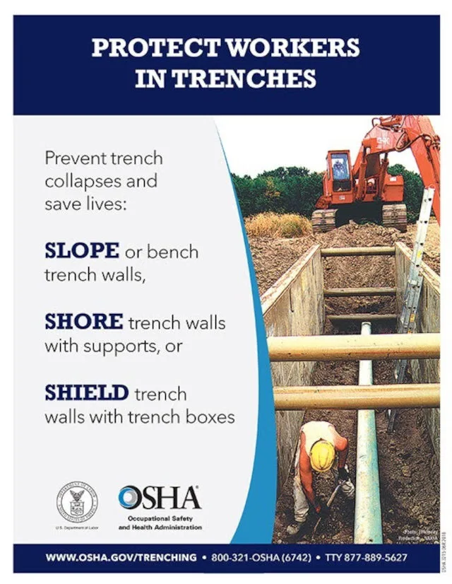
Occupational Safety & Health Administration awareness
Daily inspections by a Safety Officer are crucial to verify the integrity and safety of trenches. Refer to this guideline to learn more about: The 10 Trench Safety Tips That Can Save A Life.
DAILY INSPECTIONS
Appointing a Safety Officer to conduct daily inspections of excavation sites ensures ongoing safety. Inspections should focus on identifying signs of soil movement, water accumulation, and checking the effectiveness of protective systems. Regular inspections help maintain a safe working environment and allow for timely identification and mitigation of potential hazards.
SAFE ACCESS AND EGRESS
Proper access and egress points must be established to enable safe entry and exit from trenches. This includes the installation of ladders, ramps, or stairways at regular intervals, ensuring no worker has to travel more than 25 feet to reach a safe exit.
HAZARD AWARENESS AND TRAINING
Comprehensive training for all workers is essential to recognize and avoid potential hazards associated with trenching and excavation. Training should cover safe practices for working in and around trenches, understanding soil types, and correct equipment usage. Emphasizing the importance of not placing materials too close to trench edges prevents accidental falls and collapses.
Here’s a quality video, “Trenching and Shoring Safety Video from SafetyVideos.com” discussing this:
Embed: https://youtu.be/92ngMAFcEtU?si=Azk1OjNdsto_InVg
We’ll add our own video covering trenching and excavation for this specific structure when we construct it.
VIDEO COMING: TRENCHING AND EXCAVATION TRAINING VIDEO
SEE OUR HOW TO HELP AND/OR CROWDFUNDING CAMPAIGN PAGE TO HELP CREATE ALL THE TUTORIAL VIDEOS FASTER
EMERGENCY PREPAREDNESS
Having a clear emergency plan in place is crucial for quickly and effectively responding to incidents such as trench collapses. Workers should be trained on emergency procedures, and rescue equipment should be readily accessible on site. Regular drills can help to ensure that everyone knows their role in an emergency.
By adhering to these safety measures, the Ultimate Classroom construction site can maintain a high standard of safety, protecting the well-being of all personnel involved. For more detailed information on trenching and excavation safety, refer to OSHA’s Trenching and Excavation Safety guidelines.
Implementing these practices ensures that our project progresses smoothly while maintaining the highest safety standards, safeguarding everyone involved.
SITE PREPARATION
Begin by clearing the construction site of debris, vegetation, and topsoil. This step will give us a stable and level base for the footer construction. The video below gives an insightful tutorial on how to ‘lay out’ a building from scratch, which includes the site preparation process.

MARKING AND EXCAVATION
Mark the exact locations for the footers based on the building plan. Excavate trenches or holes to the required depth and width, considering the site’s frost line, groundwater table, and soil type.
Typically, footers are about 24 inches wide and 12 inches deep. Accurate marking and excavation are crucial for ensuring the building’s stability.
VIDEO COMING: SITE MARKING AND EXCAVATION VIDEO
SEE OUR HOW TO HELP AND/OR CROWDFUNDING CAMPAIGN PAGE TO HELP CREATE ALL THE TUTORIAL VIDEOS FASTER
FORMWORK AND REINFORCEMENT
Formwork in construction is a crucial component that ensures the concrete takes on the desired shape and structural integrity. Formwork refers to temporary or permanent molds into which concrete is poured and allowed to harden. It is essential for constructing various parts of a building, such as foundations, floors, walls, columns, and beams.
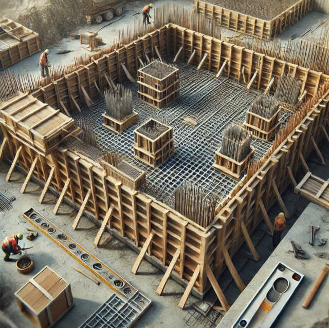 AI-generated formwork image to be replaced with actual site formwork
In the Ultimate Classroom project, selecting the appropriate formwork system and ensuring its proper installation is vital to achieving the high-quality, durable structure we aim for. Here’s an in-depth look into formwork and its application in our project:
MATERIALS USED IN FORMWORK
We will look into the different types of materials that can be used as formwork and possible options for the Ultimate Classroom project.
- TIMBER FORMWORK: Commonly used for versatility and ease of assembly. Ideal for small-scale projects or custom shapes due to its flexibility.
- STEEL FORMWORK: Known for its strength, durability, and reusability. Suitable for large-scale projects and repetitive tasks, providing a smooth finish to concrete surfaces.
- PLASTIC FORMWORK: Lightweight and easy to handle. Beneficial for projects requiring fast setup and tear-down.
- COMPOSITE MATERIALS: Combining the benefits of timber, steel, and plastic, offering flexibility, strength, and ease of use.
TYPES OF FORMWORK
- TRADITIONAL TIMBER FORMWORK: Cost-effective and adaptable, though not as durable as other types.
- ENGINEERED FORMWORK SYSTEMS: Prefabricated and modular, these systems allow for quick assembly and disassembly, improving efficiency on site.
- STAY-IN-PLACE FORMWORK: Permanent formwork that remains as part of the structure, often used in specific applications like bridges.
- SLIP FORM: A continuous formwork system that moves during the pouring process, ideal for tall structures like silos and towers.
DESIGN CONSIDERATIONS
When designing formwork, it is critical to account for the pressure and weight of wet concrete, as well as additional loads from workers and equipment. Proper bracing and support are essential to prevent formwork failure, which can lead to structural defects or safety hazards.
ASSEMBLY AND REMOVAL
Efficient formwork systems are designed for ease of assembly and disassembly. Components with quick-release mechanisms can reduce labor costs and construction time significantly. Once the concrete has achieved sufficient strength, the formwork is carefully removed to avoid damaging the newly formed structure.
VIDEO COMING: FORMWORK ASSEMBLY VIDEO
SEE OUR HOW TO HELP AND/OR CROWDFUNDING CAMPAIGN PAGE TO HELP CREATE ALL THE TUTORIAL VIDEOS FASTER
SAFETY AND QUALITY
Ensuring worker safety and the quality of the final concrete structure are paramount. Properly constructed formwork prevents leaks and deformation, leading to a better surface finish and overall structural integrity. For the Ultimate Classroom project, adhering to these principles ensures that the building process remains safe and the end product meets high-quality standards of durability and precision.
VIDEO COMING: FINAL FORMWORK AND INSPECTION BEFORE POURING CONCRETE VIDEO
SEE OUR HOW TO HELP AND/OR CROWDFUNDING CAMPAIGN PAGE TO HELP CREATE ALL THE TUTORIAL VIDEOS FASTER
POURING CONCRETE
Pour concrete into the formwork, ensuring it is evenly distributed and compacted to eliminate voids. Proper pouring techniques are required and essential to create a uniform and strong footer. This resource gives valuable tips to successfully set up the required formwork and pouring of concrete: How to Pour a Concrete Slab Foundation successfully or in PDF format.
VIDEO COMING: CONCRETE POURING VIDEO
SEE OUR HOW TO HELP AND/OR CROWDFUNDING CAMPAIGN PAGE TO HELP CREATE ALL THE TUTORIAL VIDEOS FASTER
CURING AND QUALITY CHECKS
Allow the concrete to cure and gain strength. Perform quality checks to ensure the foundation meets design specifications. Proper curing is vital for the concrete’s durability. A video of the curing techniques applied on site is to be embedded below during the construction phase.
VIDEO COMING: CURING AND QUALITY CHECKS VIDEO
SEE OUR HOW TO HELP AND/OR CROWDFUNDING CAMPAIGN PAGE TO HELP CREATE ALL THE TUTORIAL VIDEOS FASTER
FOUNDATION CONSTRUCTION
For an in-depth understanding of constructing foundations for cob houses and straw bale structures, we have included a comprehensive video in our tutorial. This resource will provide detailed insights into the nuances of foundation construction, including essential techniques, material choices, and best practices tailored to sustainable building methods.
The Ultimate Classroom utilizes a thickened-edge slab-on-grade foundation, where the footers and foundation are poured as a monolithic structure. This approach integrates the footers into the foundation, simplifying construction and reducing material usage.
SOIL AND LOAD ANALYSIS
Conduct a thorough soil analysis to determine its soil bearing capacity. Use this information to design the foundation to handle the expected loads, including live, dead, wind, and seismic loads. Ensure compliance with ACI 318 and relevant local codes, such as California’s building codes. The geotechnical team will conduct this soil analysis and video embedded below during the construction phase.
VIDEO COMING: GEOTECHNICAL SOIL ANALYSIS ON SITE VIDEO
SEE OUR HOW TO HELP AND/OR CROWDFUNDING CAMPAIGN PAGE TO HELP CREATE ALL THE TUTORIAL VIDEOS FASTER
FOUNDATION EXCAVATION
Excavate the foundation area according to the design specifications. Ensure the excavation depth accommodates the thickened edges of the slab and provides adequate support for the building. Typically, the foundation depth will be around 12 inches for the slab and 24 inches for the thickened edges.
VIDEO COMING: FOUNDATION EXCAVATION STEP-BY-STEP TUTORIAL VIDEO….
SEE OUR HOW TO HELP AND/OR CROWDFUNDING CAMPAIGN PAGE TO HELP CREATE ALL THE TUTORIAL VIDEOS FASTER
FORMWORK AND REINFORCEMENT
Set up formwork for the foundation and place reinforcement bars as specified in the design. The reinforcement should extend into the thickened edges and footers to provide additional strength.
POURING CONCRETE
Pour concrete into the foundation formwork, ensuring a continuous pour for uniformity. Use vibrators to compact the concrete and eliminate air pockets.
VIDEO COMING: CASTING CONCRETE FOR THE FOUNDATION….
SEE OUR HOW TO HELP AND/OR CROWDFUNDING CAMPAIGN PAGE TO HELP CREATE ALL THE TUTORIAL VIDEOS FASTER
CURING
Curing is a critical step in the construction of a straw bale classroom with a concrete foundation system, as it significantly impacts the strength and durability of the concrete. Proper curing ensures that the concrete maintains adequate moisture, temperature, and time to develop its intended properties.
VIDEO COMING: CURING STAGES TIME LAPSE VIDEO
SEE OUR HOW TO HELP AND/OR CROWDFUNDING CAMPAIGN PAGE TO HELP CREATE ALL THE TUTORIAL VIDEOS FASTER
INITIAL CURING
Initial curing is essential immediately after finishing the concrete surface to promote proper strength development and minimize cracking.
- Immediately after finishing the concrete surface, it is essential to start the curing process. The goal is to maintain adequate moisture content to prevent cracking and ensure strength development.
- Cover the surface with wet burlap, plastic sheeting, or a curing compound to prevent rapid moisture loss. This should be done within the first few hours after finishing the surface.
CONTINUOUS MOISTURE MAINTENANCE
Concrete should be kept continuously moist during the curing period to achieve the required strength and durability.
- For at least the first 7 days, keep the concrete continuously moist. This can be achieved by regularly sprinkling water on the surface or covering it with water-saturated materials like burlap.
- In hot and windy conditions, it is particularly important to ensure that the concrete surface does not dry out too quickly. Using evaporation retardants can help in such conditions.
USE OF CURING COMPOUNDS
Curing compounds provide an effective alternative when continuous water curing is not practical.
- Curing compounds can be applied to the surface to form a thin film that reduces moisture loss. These compounds are particularly useful when continuous water curing is impractical.
- Apply the curing compound evenly and in accordance with the manufacturer’s specifications.
VIDEO COMING: CURING COMPOUND APPLICATION VIDEO
SEE OUR HOW TO HELP AND/OR CROWDFUNDING CAMPAIGN PAGE TO HELP CREATE ALL THE TUTORIAL VIDEOS FASTER
TEMPERATURE CONTROL
- Concrete should be kept at an appropriate temperature during curing. In cold weather, protect the concrete from freezing by using insulating blankets or heated enclosures.
- In hot weather, prevent the concrete from overheating by shading the area or using cool water for curing.
VIDEO COMING: CONCRETE CURING PROCESS AND INFLUENCE ON RESULTING CONCRETE STRENGTH…
SEE OUR HOW TO HELP AND/OR CROWDFUNDING CAMPAIGN PAGE TO HELP CREATE ALL THE TUTORIAL VIDEOS FASTER
INSPECTIONS
Regular inspections are crucial to ensure the quality and integrity of the construction process. Inspections should be carried out at various stages to confirm compliance with design specifications and building codes.
PRE-POUR INSPECTION
Perform a thorough inspection before pouring concrete to ensure the foundation is ready for a successful placement.
- Before pouring concrete, inspect the formwork, reinforcement, and embedded items to ensure they are properly installed according to the plans and specifications.
- Check that the formwork is clean and free of debris, and that reinforcement is properly placed and secured.
VIDEO COMING: PRE-POUR INSPECTION VIDEO
SEE OUR HOW TO HELP AND/OR CROWDFUNDING CAMPAIGN PAGE TO HELP CREATE ALL THE TUTORIAL VIDEOS FASTER
DURING POUR INSPECTION
Monitor the concrete placement process to ensure the concrete is placed, consolidated, and finished according to project requirements.
- Monitor the concrete placement process to ensure proper consolidation and avoid segregation. Use vibration tools appropriately to eliminate air pockets and achieve uniform density.
- Verify that the concrete mix being delivered matches the specified mix design and that it is placed and finished within the allowable time frame.
POST-POUR INSPECTION
Inspect the completed concrete after placement to verify its quality and ensure that proper curing procedures have been initiated.
- After pouring, inspect the concrete surface for defects such as cracks, honeycombing, or segregation. Any issues should be addressed immediately.
- Ensure that the curing process is initiated promptly and is maintained as specified. Document the curing methods used and the duration of curing.
VIDEO COMING: POST-POUR INSPECTION VIDEO
SEE OUR HOW TO HELP AND/OR CROWDFUNDING CAMPAIGN PAGE TO HELP CREATE ALL THE TUTORIAL VIDEOS FASTER
FINAL INSPECTION
Perform a final inspection after the concrete has cured to verify that the foundation meets the required quality and performance standards before continuing construction.
- Once the concrete has cured and achieved sufficient strength, perform a final inspection to check for any surface defects or irregularities.
- Confirm that the concrete elements meet the required strength and quality standards before proceeding with any additional construction activities.
- If surface defects or irregularities are identified, refer to the brief repair guide provided below.
VIDEO COMING: FINAL INSPECTION VIDEO
SEE OUR HOW TO HELP AND/OR CROWDFUNDING CAMPAIGN PAGE TO HELP CREATE ALL THE TUTORIAL VIDEOS FASTER
REPAIR METHODS SELECTION
Ensuring the long-term serviceability of any structure requires a well-thought-out approach to addressing potential damages or wear. The selection of appropriate repair methods is crucial to maintaining the structural integrity, functionality, and safety of the Ultimate Classroom.
VIDEO COMING: CRACKS, HONEYCOMBING, SPALLING & SURFACE SCALING REPAIR VIDEO(IF ANY)
SEE OUR HOW TO HELP AND/OR CROWDFUNDING CAMPAIGN PAGE TO HELP CREATE ALL THE TUTORIAL VIDEOS FASTER
CRACKS
Cracks should be repaired based on their severity to maintain the structural integrity and durability of the concrete.
- Minor Cracks: Use epoxy injection, crack filler, or surface sealants.
- Major Cracks: Seek professional evaluation; use substantial repair methods.
HONEYCOMBING
Honeycombing should be addressed to restore the strength and appearance of the concrete surface.
- Shallow Defects: Patch with repair mortar or grout.
- Deep Defects: Chisel out defective concrete and refill.
SPALLING
Spalling should be evaluated and repaired to prevent further deterioration of the concrete surface.
- Minor Spalling: Remove loose material and patch.
- Severe Spalling: Remove damaged sections and replace with new concrete.
SURFACE SCALING
Surface scaling should be monitored and repaired to maintain the long-term performance of the concrete.
- Mild Scaling: Apply resurfacing compound or coating.
- Severe Scaling: Perform full resurfacing or overlay.
USE OF COMPATIBLE REPAIR MATERIALS
Ensure repair materials match the original concrete in strength, thermal expansion, and bonding.
VIDEO COMING:
POST REPAIR AND COMPATIBLE MATERIALS USED VIDEO
SEE OUR HOW TO HELP AND/OR CROWDFUNDING CAMPAIGN PAGE TO HELP CREATE ALL THE TUTORIAL VIDEOS FASTER
DOCUMENTATION AND COMPLIANCE
Maintain thorough documentation and ensure compliance throughout the construction process to support quality control and regulatory requirements.
- Maintain detailed records of all inspections, curing methods, and any issues encountered during the construction process.
- Ensure that all construction activities comply with the relevant building codes, standards, and project specifications.
- Engage a qualified inspector or engineer to conduct regular inspections and provide professional oversight throughout the project.
Following these guidelines for curing and inspections, we can ensure the successful construction of a durable and long-lasting straw bale classroom. This section integrates best practices for curing and inspections, emphasizing the importance of each step to ensure the overall quality and longevity of the construction project. For additional knowledge and understanding of the curing process, information can be found in this resource: ‘What is Curing of Concrete, Purpose and Importance?’
FLOORING SYSTEM
The image below shows a flooring system based on a slab-on-grade foundation as that of the Ultimate Classroom. Image will soon be replaced by the Ultimate Classroom Flooring during the construction phase and upon project completion.
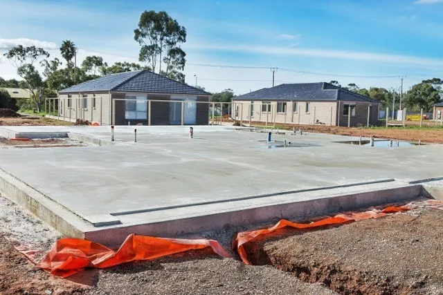
Flooring System Image to be replace with Ultimate Classroom Flooring
SUBFLOOR PREPARATION FOR SLAB-ON-GRADE
Subfloor preparation is a critical step in the construction of concrete slabs on grade, as it provides the foundational support required for a durable and stable floor. Proper preparation ensures that the concrete slab will carry the intended loads without significant settlement or structural issues. This tutorial will guide you through the steps necessary for effective subfloor preparation.
ASSESS THE SUB-GRADE:
- The subgrade is the natural ground on which the concrete slab will be built. It is essential to assess its condition to determine if any improvements are needed.
- Key considerations include soil type, bearing capacity, and moisture content. Poor subgrade conditions can lead to slab failure.
VIDEO COMING: SUB-GRADE ASSESSMENT VIDEO
SEE OUR HOW TO HELP AND/OR CROWDFUNDING CAMPAIGN PAGE TO HELP CREATE ALL THE TUTORIAL VIDEOS FASTER
IMPROVE SUBGRADE (IF NECESSARY):
- Drainage: Ensure proper drainage to prevent water accumulation that can weaken the subgrade. This might involve installing drainage systems or grading the site.
- Compaction: Use a compactor to achieve adequate soil compaction, reducing the risk of future settlement. Aim for uniform compaction across the entire area.
- Soil Stabilization: In cases of extremely poor soil, stabilize the subgrade using methods such as soil replacement, lime stabilization, or geotextiles.
INSTALL THE SUB-BASE (OPTIONAL):
- The sub-base is an additional layer placed between the subgrade and the concrete slab. It provides extra support and improves load distribution.
- Common sub-base materials include gravel, crushed stone, or recycled concrete. Spread the material evenly and compact it thoroughly.
VIDEO COMING: SUB-GRADE INSTALLATION VIDEO
SEE OUR HOW TO HELP AND/OR CROWDFUNDING CAMPAIGN PAGE TO HELP CREATE ALL THE TUTORIAL VIDEOS FASTER
PROOF ROLL THE SUB-BASE:
- Proof rolling involves driving a loaded vehicle over the sub-base to identify soft spots or areas requiring further compaction. Address any deficiencies before proceeding.
PLACE VAPOR BARRIER (IF NEEDED):
- For indoor or moisture-sensitive environments, install a vapor barrier, such as plastic sheeting, over the sub-base. This prevents moisture from migrating upward into the slab.
VIDEO COMING: PLACING OF VAPOR BARRIER FOR REINFORCED CONCRETE SLAB….
SEE OUR HOW TO HELP AND/OR CROWDFUNDING CAMPAIGN PAGE TO HELP CREATE ALL THE TUTORIAL VIDEOS FASTER
SET UP FORMS:
- Install wooden or metal forms around the perimeter of the area where the slab will be poured. Ensure they are level and securely anchored.
VIDEO COMING: SLAB-ON-GRADE FORMWORK VIDEO
SEE OUR HOW TO HELP AND/OR CROWDFUNDING CAMPAIGN PAGE TO HELP CREATE ALL THE TUTORIAL VIDEOS FASTER
REINFORCEMENT:
- Depending on the design requirements, place reinforcement such as rebar or wire mesh within the forms. This provides additional strength and crack resistance to the slab.
VIDEO COMING: SLAB REINFORCEMENT INSPECTION VIDEO
SEE OUR HOW TO HELP AND/OR CROWDFUNDING CAMPAIGN PAGE TO HELP CREATE ALL THE TUTORIAL VIDEOS FASTER
FINAL INSPECTION:
Conduct a thorough inspection to ensure all preparation steps have been correctly followed. Verify compaction, levelness, and the placement of the vapor barrier and reinforcement.
ROCKWOOL INSULATION
Install Rockwool Insulation over the subfloor. Rockwool is an excellent choice due to its high thermal resistance, sound absorption properties, and fire resistance. Ensure the insulation is evenly distributed and securely placed. The thickness of the Rockwool can vary, but 3-4 inches is typically used.
VIDEO COMING: ROCKWOOL INSULATION ON-SITE INSTALLATION PROCESS
SEE OUR HOW TO HELP AND/OR CROWDFUNDING CAMPAIGN PAGE TO HELP CREATE ALL THE TUTORIAL VIDEOS FASTER
CONCRETE SLAB
Pour the concrete slab over the Rockwool insulation. This slab serves as the finished floor surface, providing a durable and easy-to-maintain flooring option. Ensure proper leveling and finishing techniques are applied. Typically, the slab will be at least 4 – 6 inches thick.
VIDEO COMING: FINAL POUR INCLUDING INSULATION VIDEO
SEE OUR HOW TO HELP AND/OR CROWDFUNDING CAMPAIGN PAGE TO HELP CREATE ALL THE TUTORIAL VIDEOS FASTER
CURING AND FINISHING
Allow the concrete slab to cure. Apply finishing treatments as needed to achieve the desired surface texture and appearance.
VIDEO COMING: FINAL CURING AND FINISHES OR THE ULTIMATE CLASSROOM FOUNDATION AND FLOORING VIDEO
SEE OUR HOW TO HELP AND/OR CROWDFUNDING CAMPAIGN PAGE TO HELP CREATE ALL THE TUTORIAL VIDEOS FASTER
By following these steps, you can construct a sturdy and well-insulated foundation and flooring system for the Ultimate Classroom. Each phase of the process is designed to ensure long-term durability and performance, making it an ideal choice for sustainable and efficient construction.
CONCLUSION
Constructing the Ultimate Classroom has been a comprehensive journey that encompasses detailed planning, precise execution, adherence to high standards of engineering and sustainability. This tutorial has provided a step-by-step guide to build a durable and efficient structure using straw bale construction techniques, with a focus on replicability for global adoption.
FROM SITE PREPARATION TO FINISHING TOUCHES
This guide covers all essential phases, from the initial site preparation and excavation, through to the construction of footers, foundations, and flooring systems. Each step has been meticulously detailed to ensure clarity and ease of understanding, enabling anyone with basic construction knowledge to follow along.
EMPHASIZING COMPLIANCE AND SAFETY
Throughout the project, compliance with ACI 318 standards and local California codes has been a priority. By integrating these regulatory frameworks into the design and construction process, we ensure that the structure meets all necessary safety and performance requirements.
INNOVATIVE USE OF MATERIALS
The use of Rockwool insulation and a monolithic slab-on-grade foundation highlights our commitment to sustainable and energy-efficient building practices. These materials not only enhance the thermal performance of the building but also contribute to its overall durability and safety.
REPLICABILITY AND EDUCATION
One of the primary goals of the Ultimate Classroom project is to demystify straw bale construction and provide a clear, replicable path for others to follow. This report serves as both an instructional manual and an inspirational guide, encouraging wide adoption of sustainable building practices.
Builders, educators, and sustainability advocates can choose to follow this detailed tutorial to construct their own versions of the Ultimate Classroom, contributing to a more sustainable and environmentally conscious future.
RESOURCES & REFERENCES
This section provides a comprehensive list of all the resources referenced throughout this report. These resources will be invaluable to anyone looking to replicate the Ultimate Classroom project, offering essential guidelines, standards, and methodologies for sustainable construction processes.
- Article – Differences Between Stem Wall and Monolithic Foundations
- Article – Slab Foundations
- Article – Straw Bale Construction – Commonly Used Foundations
- Article – Structural Design of Foundations
- Article – Choosing the Right Footings for Strong Foundations
- ACI 318 – 2019 Code
- CALGreen Building Code Guide First Edition 2010
- CALGreen Low-Rise Residential comparison to GreenPoint Rated and LEED for Homes
- ASCE 7-16 General Load Combinations
- Hardwood Floors in a Straw Bale House
- Use Concrete Slab as Finished Flooring
- ASCE 7 – 10 Code
- Determining Wind Loads in relation to Building Design and Construction
- Wind Load Calculation as per ASCE 7 – 16
- How to Pour a Concrete Slab Successfully
- What is Curing Concrete – Purpose, Importance, Curing Methods
- Ultimate Classroom Foundation Report
SUMMARY
The Ultimate Classroom Foundation, Footer, and Flooring Design encapsulates the comprehensive efforts to create an innovative, sustainable, and replicable construction process for the Ultimate Classroom. This report synthesizes detailed analyses, including wind load considerations, material selection, and foundation design, adhering to industry standards such as ASCE 7-16, ACI 318, and relevant local codes.
The design prioritizes structural integrity, sustainability, and cost-efficiency, employing shallow foundations and a slab-on-grade flooring system tailored for durability and functionality. By addressing essential aspects like repair methods, load assumptions, and construction practices, this report aims to provide a clear, instructional guide for stakeholders and aspiring builders. Ultimately, it serves as a critical resource to support the open-sourcing initiative, enabling wider adoption of innovative, eco-friendly building techniques.
FREQUENTLY ANSWERED QUESTIONS
Q: What is the Ultimate Classroom, and what makes it unique?
The Ultimate Classroom is a sustainable, open-source design project focused on creating eco-friendly, straw bale construction classrooms. It emphasizes cost-efficiency, replicability, and sustainability, making it ideal for educational and community-focused settings.
Q: What are the primary materials used in the Ultimate Classroom?
The primary materials include straw bales and reinforced concrete, combined with a slab-on-grade flooring system. These materials are chosen for their environmental benefits, insulation properties, and durability.
Q: What type of foundation is used, and why?
The design utilizes shallow foundations due to their cost-effectiveness and suitability for the load conditions of the Ultimate Classroom. This approach ensures structural stability while minimizing material usage.
Q: How does the design account for wind and other environmental loads?
The Ultimate Classroom follows ASCE 7-16 standards to calculate wind and other environmental loads. These calculations ensure the structure can withstand forces such as high wind speeds while maintaining safety and integrity.
Q: What is the purpose of this report and tutorial?
This report serves as a comprehensive guide to designing and constructing the Ultimate Classroom. It provides calculations, code references, and step-by-step instructions to make the project accessible to individuals and organizations worldwide for DIY replication.
Q: How does the project promote sustainability?
The Ultimate Classroom incorporates eco-friendly materials and energy-efficient design principles. The use of straw bales, natural insulation, and local resources significantly reduces the project’s environmental footprint.
Q: Can the design be modified for different climates or needs?
Yes, the Ultimate Classroom’s design is adaptable. The report provides guidelines for modifying construction details to suit varying climates, soil conditions, and functional requirements.
Q: What codes and standards are referenced in the design?
The design adheres to ASCE 7-16, ACI 318, and other relevant local building codes. These standards ensure the structure’s safety, durability, and compliance with engineering best practices.
Q: Is the project suitable for non-professionals or DIY builders?
Yes, the open-source tutorial includes simplified explanations, diagrams, and practical steps to help non-professionals and DIY enthusiasts understand and replicate the construction process.
Q: How can I access the complete design and construction guide?
The full tutorial and engineering report, including all calculations, drawings, and step-by-step guidance, are available as an open-source resource through the Ultimate Classroom initiative. Links to additional resources and files are provided in the report.