 One Community
Duplicable City Center Engineering
One Community is designing an open source and free-shared Duplicable City Center to save resources and help model a redefinition of how people choose to live. This page will explain the process of calculating and designing all the structural engineering details with the following sections:
- What is Structural Engineering
- Why Open Source Structural Engineering
- Ways to Contribute to this Open Source Component
- Key Consultants to this Component of One Community
- Duplicable City Center Structural Engineering Details
- 2 References
- 2.1 Codes and Regulations
- 2.2 Standards, Specifications, and Material Specifications
- 2.2.1 Material Specifications
- 2.2.2 International Code Council, ICC g2-2010 Guidline for Acoustics
- 2.2.3 Aluminum Association
- 2.2.4 American Society of Heating, Refrigerating and Air-Conditioning Engineers
- 2.2.5 Ceilings and Interior Systems Construction Association
- 2.2.6 National Roofing Contractors Association
- 2.2.7 Steel Deck Institute
- 2.2.8 Ceilings and Interior System Construction Association
- 2.2.9 Glass Association of North America
- 2.3 Drawings
- 3 Definitions and Nomenclatures
- 4 Duplicable City Center Conceptual Design
- 5 Architectural Design Specifications
- 6 Structural Design Specifications/Loading Specifications
- 6.1 Risk Category
- 6.2 Load Combinations
- 6.3 Dead Loads
- 6.4 Live Loads
- 6.5 Snow Load
- 6.6 Rain Load
- 6.7 Ice Load
- 6.8 Seismic Design Criteria
- 6.8.1 Seismic Ground Motion Values
- 6.8.2 Site Class
- 6.8.3 Average Shear Wave Velocity
- 6.8.4 Site Coefficient and Risk-Targeted
- 6.8.5 Design Spectral Acceleration Parameters
- 6.8.6 Seismic Design Category
- 6.8.7 Geohazard and Geotechnical Investigation
- 6.8.8 Seismic Design Requirements for Building Structures
- 6.8.9 Seismic Design Requirements for Nonstructural Components
- 6.8.10 Building Lateral Resisting System
- 7 Civil Design Specifications
- 8 Mechanical Design Specifications
- 9 Plumbing Design Specifications
- 10 Electrical Design Specifications
- 11 Instrumentation Design Specifications
- 12 Planning
- 13 Construction
- 14 Inspection
- 15 Water-Based Fire Suppression Systems
- 16 Digital Addressable Fire Alarm System
- 17 Appendix A – 1 – Document Control
- Resources
- Summary
- FAQ
NOTE: THIS PAGE IS NOT CONSIDERED BY US TO BE A COMPLETE AND USABLE TUTORIAL UNTIL
WE FINISH OUR OWN CONSTRUCTION OF THIS COMPONENT, CONFIRM ALL THE DETAILS, AND ADD
TO THIS PAGE ALL THE RELATED VIDEOS, EXPERIENCE, AND OTHER UPDATES FROM THAT BUILD.
IN THE MEANTIME, YOU CAN HELP US COMPLETE IT ALL SOONER WITH THE FOLLOWING OPTIONS:
INPUT & FEEDBACK | JOIN OUR TEAM | HELP US BUY THE PROPERTY
RELATED PAGES (Click icons for complete pages)
")
")
")
")
")
")
")
CLICK ICONS BELOW TO JOIN US THROUGH SOCIAL MEDIA
![]()
![]()
![]()
![]()
![]()
![]()
![]()
![]()
![]()
![]()
WHAT IS STRUCTURAL ENGINEERING
 Structural engineering, a subfield of civil engineering, applies the principles of physics, mathematics, and empirical expertise to safely design the framework and load-bearing components of human-made structures. In contemporary times, it encompasses a comprehensive and intricate knowledge base that can precisely anticipate how various shapes and materials employed in structures will withstand external forces and stress. These principles of structural engineering have been employed since ancient times, as evidenced by the construction of iconic structures such as the Egyptian pyramids and the Greek Acropolis, thousands of years ago.
WHY OPEN SOURCE
STRUCTURAL ENGINEERING
Opening up the field of structural engineering to open-source principles can revolutionize the way we design and build our infrastructure. By sharing knowledge, processes, and tools openly, we foster collaboration among experts worldwide, democratize access to cutting-edge technology, and accelerate innovation. This approach not only ensures that best practices are widely accessible but also invites scrutiny and peer review, leading to safer and more efficient designs. Additionally, open-source structural engineering promotes cost-efficiency, making it easier for communities with limited resources to access the expertise needed for sustainable development. In an era where climate change and resource constraints demand creative solutions, open-sourcing structural engineering can pave the way for a more resilient, adaptable, and equitable built environment, benefiting society as a whole.
Sharing the plans and research for projects like the Duplicable City Center is important so that other engineers and designers can use our ideas to make their own projects even better. This collaborative approach not only promotes knowledge sharing but also accelerates the development of sustainable and adaptable solutions that can address the evolving challenges of urban development and infrastructure in an increasingly interconnected world.
WAYS TO CONTRIBUTE TO EVOLVING THIS SUSTAINABILITY COMPONENT WITH US
SUGGESTIONS | CONSULTING | MEMBERSHIP | OTHER OPTIONS
KEY CONSULTANTS TO THE STRUCTURAL ENGINEERING DETAILS FOR THIS STRUCTURE
Haoxuan “Hayes” Lei: Structural Engineer
Jin Yu: Structural Engineering Designer
Shuna Ni: Structural Engineer
Zhide Wang: Mechanical Engineer
Charles Gooley: Web Designer
Julia Meaney: Web and Content Reviewer and Editor
DUPLICABLE CITY CENTER
STRUCTURAL ENGINEERING DETAILS
One Community is designing an open source and free-shared Duplicable City Center® to help model a redefinition of how people choose to live, save resources, and function as a revenue generator and starting point for DIY and replicable sustainable city construction. It will open source 15 different templates and function as a recreation center, large-scale dining hall, large-scale laundry facility, and alternative for visitors that might not (at first) be comfortable staying in the Earthbag Village or Straw Bale Village.
1.1. WHAT IS A DUPLIABLE CITY CENTER
Once complete, the Duplicable City Center will be the largest open source/DIY structure in the world. As part of One Community, it will be a diversely functional, ultra-eco-friendly (LEED Platinum Certifiable), space and resource saving community center designed to be replicated. It is meant to be (but doesn’t need to be) built as the central and/or starting point of any one of the seven (7) One Community sustainable village models. Its purpose is to support a redefinition of how people live by providing a space more beautiful than most people’s homes that replaces the need for individual kitchens, living rooms, laundry rooms, and other in-home recreation spaces. It is also purposed to function in conjunction with One Community’s open source nonprofit and for-profit business models as both a non-profit teacher/demonstration community, village, or city center and/or the central structure of an eco-tourism destination. To our knowledge, it will also be the first open source and DIY commercial building ever to be built.
1.2. WHY CREATE AN OPEN SOURCE DUPLICABLE CITY CENTER
Building a duplicable city center is an opportunity for people to improve their way of living through investing resources in shared space. As part of One Community’s 4-phase global change strategy, we will demonstrate building a city center like this as providing five (5) primary benefits:
- It saves huge amounts of money and resources
- It builds Community and supports a sharing and cooperative mentality
- It is an excellent launch point for teacher/demonstration hubs to be built around the world
- It is an ultra-sustainable and modern option that will appeal to many people who might not otherwise consider joining the self-replicating teacher/demonstration community, village, and city movement. It is also brandable for people who want to make eco-tourism a revenue producing component of their off-grid strategy
- Increased affordability through our open source do-it-yourself plans and provides 15 templates for replicating all the components including complete DIY structure assembly, hydronic systems setup, the natural pool and eco hot tub, eco-laundry for 300+ people, eco-kitchen for 400+ people, DIY pallet furniture, climate battery design and implementation, advanced control and automation, sustainable energy infrastructure, LEED Platinum lighting design, LEED Platinum HVAC design, LEED Platinum materials selection and acquisition, and eco-tourism revenue generation for community construction and expansion using this structure and the other 7 villages models
In traditional society, each family home contains space for socializing with friends, preparing and eating meals, and doing laundry. We believe that we will save significant space and resources by providing shared access to a high-quality environment for these activities within our City Center instead. This, in accordance with our global change methodology, creates another path to the One Community global-change model spreading on its own. Here’s a video tour of the structure and why we think people will be happy for this alternative to traditional housing models:
The Duplicable City Center Open Source Portal (Collaborative resource and information hub)
WHO IS THE POTENTIAL AUDIENCE
This resource, tutorial, and structure are for:
- Any people who would like to develop a sustainable community themselves
- Any students who would like to learn relevant knowledge in city developments
- Any governments that would like to develop a creative, sustainable city in original places
- Any property developers who would like to build up a group of buildings in a brand new area
- Any non-profit organization to rebuild a city after disaster situations
2. REFERENCES
2.1. CODES AND REGULATIONS
2.1.1. FEDERAL/NATIONAL REGULATIONS
- 2.1.1.1 International Zoning Code (IZC) 2018
- 2.1.1.2 International Building Code 2019
- 2.1.1.3 2.1.1.3 Cal-OSHA 29 CFR 1910 ” Occupational Safety and Health Standards
- 2.1.1.4 Cal-OSHA 29 CFR 1926 ” Safety and Health Regulations for Construction
- 2.1.1.5 U.S. Department of Justice (DOJ) – Americans with Disabilities Act (ADA)
- 2.1.1.6 ADA Standards for Accessible Design Guidance on the ADA Standards for Accessible Design
- 2.1.1.7 National Fire Protection Association (NFPA)
- 2.1.1.7.1 NFPA 10 – Standard for Portable Fire Extinguishers
- 2.1.1.7.2 NFPA 13 – Standard for the Installation of Sprinkler Systems
- 2.1.1.7.3 NFPA 14 – Standard for the Installation of Standpipe and Hose Systems
- 2.1.1.7.4 NFPA 45 – Standard on Fire Protection for Laboratories Using Chemicals
- 2.1.1.7.5 NFPA 70 – National Electrical Code (NEC)
- 2.1.1.7.6 NFPA 72 – National Fire Alarm and Signaling Code
- 2.1.1.7.7 NFPA 75 – Standard for the Fire Protection of Information Technology Equipment
- 2.1.1.7.8 NFPA 80 – Standard for Fire Doors and Other Opening Protectives
- 2.1.1.7.9 NFPA 90A – Standard for the Installation of Air-Conditioning and Ventilating Systems
- 2.1.1.7.11 NFPA 101 – Life Safety CodeNFPA 90A – Standard for the Installation of Air-Conditioning and Ventilating Systems
- 2.1.1.7.10 NFPA 91 – NFPA 91 – Standard for Exhaust Systems for Air Conveying, of Vapors, Gases, Mists, and Noncombustible Particulate Solids
- 2.1.1.7.12 NFPA 252 – Standard Methods of Fire Tests of Door Assemblies
- 2.1.1.7.13 NFPA 2001 – Standard on Clean Agent Fire Extinguishing Systems
- 2.1.1.8 SEI/ASCE7-16 ” Minimum Design Loads for Buildings and Other Structures:
- ANSI/ASCE 7-16 ” New York: American Society of Civil Engineers, 2010
- 2.1.1.9 SEI/ASCE 37-02 ” Design Loads on Structures during Construction
- 2.1.1.10 American Society of Mechanical Engineers (ASME)
- 2.1.1.10.1 ASME A17.1 – Safety Code for Elevators and Escalators
- 2.1.1.10.2 ASME B30.2 – Overhead and Gantry Cranes (Top Running Bridge, Single or Multiple Girder, Top Running Trolley Hoist)
- 2.1.1.10.3 ASME B30.11 – Monorails and Underhung Cranes
- 2.1.1.11 Institute of Electrical and Electronic Engineers (IEEE)
- 2.1.1.11.1 IEEE 1100 – Recommended Practice for Powering and Grounding Electronic
- 2.1.1.12 American Welding Society (AWS)
- 2.1.1.12.1 AWS D1.1/D1.1M – Structural Welding Code-Steel
- 2.1.1.12.2 AWS D1.3/D1.3M – Structural Welding Code-Sheet Steel
- 2.1.1.12.3 AWS D14.1/D14.1M – Specification for Welding of Industrial and Mill Cranes and Other Material Handling Equipment
2.1.2. STATE AND LOCAL AUTHORITIES REGULATIONS
- 2.1.2.1 City of Los Angeles ” Los Angeles Building Code (LABC) 2017 (If applicable)
- 2.1.2.2 California Building Code (CBC 2019)
- 2.1.2.3 Local Building and Safety Officials for City or County
- 2.1.2.4 California Fire Code (CFC 2016), Title 24, Part 9
- 2.1.2.5 California Plumbing Code (CPC 2016), Title 24, Part 5
2.1.3. STEEL AND COLD FORM DESIGN
- 2.1.3.1 Code of Standard Practice for Steel Buildings and Bridges (AISC 303-16). Chicago, IL: American Institute of Steel Construction, 2010
- 2.1.3.2 Specification for Structural Steel Buildings (AISC 360-10). Chicago, IL: American Institute of Steel Construction, 2010
- 2.1.3.3 Seismic Provision for Structural Steel Buildings (AISC 341-10). Chicago, IL: American Institute of Steel Construction, 2010
- 2.1.3.4 Steel Construction Manual 15th Edition
- 2.1.3.5 AISC 326 – Detailing for Steel Construction
- 2.1.3.6 Specification for Structural Joints Using ASTM A325 or A490 Bolts
- 2.1.3.7 AISI SG 673, Part I ” Specification for the Design for Cold-Formed Steel Structural Members
- 2.1.3.8 Steel Deck Institute – SDI Design Manual for Composite Decks, Form Decks and Roof Decks ” No.31
2.1.4. CONCRETE AND MASONRY DESIGN
- 2.1.4.1 American Concrete Institute ACI 318-14 ” Building Code Requirements for Structural Concrete and commentary
- 2.1.4.2 American Concrete Institute ACI 530/ASCE 5/TMS 402 – Building Code Requirements for Masonry Structures
- 2.1.4.3 American Concrete Institute (ACI) ” ACI 330R – Guide for the Design and Construction of Concrete Parking Lots
- 2.1.4.4 American Concrete Institute (ACI) ” ACI 304R – Guide for Measuring, Mixing, Transporting, and Placing Concrete, 2009
2.1.5. WOOD DESIGN
- 2.1.5.1 American Wood Council, Code Conforming Wood Design
- 2.1.5.2 American Wood Council, National Design Specification (NDS)
- 2.1.5.3 American Wood Council, Special Design Provisions for Wind and Seismic
2.1.6 THE GREEN BOOK
- Standard Specification for Public Works Construction, 2018
- Air Movement and Control Association (AMCA)
- AMCA 511 – Certified Ratings Program ” Product Rating Manual for Air Control Devices
- Institute of Electrical and Electronic Engineers (IEEE)
- IEEE 1100 – Recommended Practice for Powering and Grounding Electronic Equipment
2.2. STANDARDS, SPECIFICATIONS, AND MATERIAL SPECIFICATIONS
2.2.1. MATERIAL SPECIFICATIONS
- ASTM A992/A992M ” Standard Specification for Structural Steel Shapes
- ASTM A36/A36M ” Standard Specification for Carbon Structural Steel
- ASTM A82/A82M ” Standard Specification for Steel Wire, Plain, for Concrete Reinforcement
- ASTM A307 ” Standard Specification for Carbon Steel Bolts and Studs,60 000 PSI Tensile Strength
- ASTM F1554 ” Standard Specification for Anchor Bolts, Steel, 36, 55, and 105-ksi Yield Strength
- ASTM A325 ” Standard Specification for Structural Bolts, Steel, Heat Treated, 120/105 ksi Minimum Tensile Strength
- ASTM A490 ” Standard Specification for Structural Bolts, Alloy Steel, Heat Treated,150 ksi Minimum Tensile Strength
- ASTM A615/A615M ” Standard Specification for Deformed and Plain Carbon-Steel Bars for Concrete Reinforcement
- ASTM D1557 – Standard Test Methods for Laboratory Compaction Characteristics of Soil Using Modified Effort
- ASTM E1264 – Standard Classification for Acoustical Ceiling Products
- ASTM F1066 – Standard Specification for Vinyl Composition Floor Tile
- ASTM F1303 – Standard Specification for Sheet Vinyl Floor Covering with Backing
- ASTM F1344 – Standard Specification for Rubber Floor Tile
- ASTM F1700 – Standard Specification for Solid Vinyl Floor Tile
- ASTM F1860 – Standard Specification for Rubber Sheet Floor Covering with Backing
- ASTM F1861 – Standard Specification for Resilient Wall Base
- ASTM F2195 – Standard Specification for Linoleum Floor Tile
- ASTM E 413-16 classification for Rating Sound Insulation
2.2.2. INTERNATIONAL CODE COUNCIL, ICC G2 ” 2010 “GUIDELINE FOR ACOUSTICS”
2.2.3. ALUMINUM ASSOCIATION
- 2.2.3.1 Aluminum Design Manual
2.2.4. AMERICAN SOCIETY OF HEATING, REFRIGERATING AND AIR-CONDITIONING ENGINEERS, INC. (ASHRAE)
- 2.2.4.1 ASHRAE Handbook – Fundamentals (I-P and SI Editions)
- 2.2.4.2 ASHRAE Handbook – HVAC Applications (I-P and SI Editions)
- 2.2.4.3 ASHRAE Handbook – Refrigeration (I-P and SI Editions)
- 2.2.4.4 ASHRAE 52.2 – Method of Testing General Ventilation Air-Cleaning Devices for Removal Efficiency by Particle Size
- 2.2.4.5 ASHRAE 62.1 – Ventilation for Acceptable Indoor Air Quality
- 2.2.4.6 ASHRAE 110 – Method of Testing Performance of Laboratory Fume Hoods
- 2.2.4.7 ASHRAE 90551 – Fundamentals of HVAC Control Systems (I-P Edition)
- 2.2.4.8 ASHRAE 90552 – Fundamentals of HVAC Control Systems (SI Edition)
2.2.5. CEILINGS AND INTERIOR CONSTRUCTION ASSOCIATION (CISCA)
- 2.2.5.1 Ceiling Systems Handbook
- 2.2.5.2 Recommended Test Procedures for Access Floors
- 2.2.5.3 Equipment
2.2.6. NATIONAL ROOFING CONTRACTORS ASSOCIATION (NRCA)
- 2.2.6.1 The NRCA Roofing Manual: Steep-slope Roof Systems
- 2.2.6.2 The NRCA Roofing Manual: Metal Panel and SPF Roof Systems
- 2.2.6.3 The NRCA Roofing Manual: Membrane Roof Systems
- 2.2.6.4 The NRCA Roofing Manual: Architectural Metal Flashing, Condensation Control and Reroofing
- 2.2.6.5 NRCA Vegetative Roof Systems Manual
2.2.7. STEEL DECK ASSOCIATION(SDI)
- 2.2.7.1 Design Manual for Composite Decks, Form Decks and Roof Decks-No. 31
2.2.8. CEILING AND INTERIOR SYSTEM CONSTRUCTION ASSOCIATION (CISCA)
2.2.9. GLASS ASSOCIATION OF NORTH AMERICA (GANA)
- 2.2.9.1 GANA Glazing Manual
2.3. DRAWINGS
Content coming…
3. DEFINITIONS AND NOMENCLATURES
3.1. DEFINITIONS
- Owner (or Company) – One Community.
- Contractor – A Contractor is any entity under contract with Southern California Gas Company or Sempra Energy Utility, including a Subcontractor, with responsibility for performing work described in this document.
- Subcontractor – An individual or business that contracts to perform the scope of the work, which is defined and prepared by the Contractor.
- Detailed Design Engineering – Development of all required Construction Documents and drawings for IFC (Issued for Construction) stage for the construction, and detailed bill of materials (BOM) for the bulk material procurement based on the basic or Front-End-Engineering Design (FEED) package. The Detailed Design and Engineering is limited to verifying design basis but producing all Construction Documents after incorporating vendor information.
- CSA Engineering Documents – Documents which contain technical information regarding Civil, Structural, Architectural, and Geotechnical such as Design Basis/Criteria, Engineering Sketches, Conceptual Designs, Drawings, Calculations, Specifications, etc.
- Engineering Design Package – Engineering Design Package includes the Engineering Documents and Construction Documents.
- Engineering Documents – All documents including but not limited to:
Equipment Specifications, Vendor Drawings, Calculations (All disciplines), Engineering Reports (Geotechnical), Studies, Specifications, Design Criteria, Design Drawings (Conceptual), Construction Specifications, Material Specification and all other required documents which provide support and will be required to complete the project and obtain all required permits. - Construction Documents – Written, graphic and pictorial documents (Drawings) prepared or assembled for describing the design, location and physical characteristics of the elements of a project necessary for construction and obtaining a building permit (if applicable). Drawings and Specifications are considered the two (2) essential Construction Documents in this governance.
- Sr./Principal Architect – A cognizant Architect who is assigned by Civil, Structural, Architectural (CSA) Engineering Group Supervisor (EGS) with over 15 years of experience in Architectural Design. Sr. Architect shall be a licensed Architect registered in the State of California (National Council of Architectural Registration Boards NCARB).
- Architect – A cognizant Architect who is assigned by EGS or Sr. Architect with over 5 years of experience in Architectural Design.
- Building – Any structure used or intended for supporting or sheltering any use or occupancy.
- Canopy/Shelter – A permanent structure or architectural projection of rigid construction over which a covering is attached that provides weather protection, identity or decoration. A canopy is permitted to be structurally independent or supported by attachment to a building on one or more sides.
- Engineer of Record – A California Licensed Civil (P.E.) or Structural (S.E.) Engineer who is contractually obligated to sign and seal the CSA Engineering Documents.
- Inspector – The party responsible for verifying the quality of all materials, installations, and workmanship furnished by the manufacturer/supplier. The inspector shall be qualified by training and experience and hold certifications or documentation of their qualifications. Unless otherwise specified in the contract documents, the inspector shall be an independent party retained by the purchaser.
- Professional Engineer – An engineer, other than the engineer of record licensed as defined by the laws of the locality in which the building is to be constructed, and qualified to practice in the specialty discipline required for the work described in the contract documents.
- Purchaser – The party who awards the contract to provide purchase order/requisition. The purchaser may be the owner or the owner’s authorized agent.
- Principal/Sr. Structural Engineer – A cognizant Structural Engineer (Preferably with master’s degree in Structural Major) who is assigned by CSA Engineering Group Supervisor with over 15 years of experience in Structural Engineering. The Principle/Sr. Structural Engineer must be a licensed Civil or Structural engineer registered in the State of California.
- Wildland ” Urban Interface Fire Area – Wildland – urban interface fire area is a geographical area identified by the state as a “Fire Hazard Severity Zone” in accordance with the Public Resources Code Sections 4201 through 4204 and Government Code Sections 51175 through 51189, or other areas designated by the enforcing agency to be at a significant risk from wildfires.
3.2. NOMENCLATURE
- ADA – Americans with Disabilities Act
- AIA – The American Institute of Architects
- Cal-OSHA – California Occupational Safety and Health Administration
- CSA – Civil, Structural, and Architectural
- DBD – Design Basis Document
- DDE – Detailed Design Engineering
- DIY – Do-it-yourself
- EGS – Engineering Group Supervisor
- EIT – Engineer-In-Training (Certification)
- EPC – Engineering ” Procurement – Construction
- FEED – Front-End Engineering Design
- G.E. – Geotechnical Engineer (Registered/ Certification)
- HVAC – Heating, Ventilation and Air Conditioning
- ICC – International Code Council
- IFC – Issued for Construction
- IFR – Issued for Review
- ISA – International Society of Automation
- LABC – Los Angeles Building Code
- LADBS – Los Angeles Department of Building and Safety
- MAOP – Maximum Allowable Operating Pressure
- MBMA – Metal Building Manufacturers Association
- MSA – Meter Set Assembly
- NDS – National Design Specification (for Wood Construction)
- NFPA – National Fire Protection Association
- NRCA – National Roofing Contractors Association
- P.E. – Professional Engineer (Registered/Certification)
- QA/QC – Quality Assurance/Quality Control
- RR – Research Report Number (LADBS)
- SE – Structural Engineer (Registered/ Certification)
- SSI – Soil-Structure Interaction
4. DUPLICABLE CITY CENTER CONCEPTUAL DESIGN
4.1. PURPOSE
The purpose of Conceptual Design of Duplicated City Center Building (hereafter Building) can be elaborated as follow:
- Prepare Architectural plans to determining the Building envelopes (Overall Sizes)
- Determine the minimum required size of lot based on the Building envelope and other planning and zoning requirements
- Determine the proper Structural System and Structural Materials
- Determine the proper material of Building (Green Building)
- Determine the Mechanical and Electrical equipment and devices
- Determine the required instrumentation including IT and other devices
- Determine the method of Construction
- Provide the estimation for bulk material and total man-hour of the Construction (Construction Planning)
- Provide approximate budget and determine the schedule of Detailed Design phase and Construction (EPC)
4.2. LOCATIONS
The Conceptual Design is considered to be a Model Building that can be constructed at various locations. The Building will be designed in accordance with all applicable codes in the United States.
In this phase, the following locations are considered:
- State of Utah (City of Kanab and the country around it)
- State of California (County of LA, County of Orange, and County of San Diego)

Figure 1 – Considered Locations for the Model Building
4.3. ZONING AND PLANNING REQUIREMENTS
The minimum Requirement of International Zoning Code [Ref. 2.1.1.1] shall be considered.
4.4. UTILITIES
Prior to the selection of the site, the utility companies for Water & Sewage, Electricity, Gas and Communication shall be determined.
4.5. MUNICIPALITY/PUBLIC WORKS
The Municipality of the selected area (Local Jurisdiction City/County) shall be determined and contacted to obtain all applicable codes and regulations.
4.6. STRUCTURAL DESIGN CONSIDERATIONS
The Design Criteria for Structural Design will be considered as envelope of the criteria for various locations.
5. ARCHITECTURAL DESIGN SPECIFICATIONS
5.1. DEFINITIONS (ARCHITECTURAL)
- Building Area – The area included within surrounding exterior walls, or exterior and firewalls, exclusive of vent shafts and courts. Areas of the building not provided with surrounding walls shall be included in the building area if such areas are included within the horizontal projection of the roof or floor above.
- Floor Area, Gross – The floor area within the inside perimeter of the exterior walls of the building under consideration, exclusive of vent shafts and courts, without deduction for corridors, stairways, ramps, closets, the thickness of interior walls, columns or other features. The floor area of a building, or portion thereof, not provided with surrounding exterior walls shall be the usable area under the horizontal projection of the roof or floor above. The gross floor area shall not include shafts with no openings or interior courts.
- Floor Area, Net – The actual occupied area, not including unoccupied accessory areas such as corridors, stairways, ramps, toilet rooms, mechanical rooms and closets.
- Exit – That portion of a means of egress system between the exit access and the exit discharge or public way. Exit components include exterior exit doors at the level of exit discharge, interior exit stairways and ramps, exit passageways, exterior exit stairways and ramps and horizontal exits.
- Exit Access – That portion of a means of egress system that leads from any occupied portion of a building or structure to an exit.
- Exit Access Doorway – A door or access point along the path of egress that travels from an occupied room, area or space where the path of egress enters an intervening room, corridor, exit access stairway or ramp.
- Exit Access Ramps – A ramp within the exit access portion of the means of egress system.
- Exit Access Stairway – A stairway with the exit access portion of the means of egress system.
- Exit Discharge – That portion of a means of egress system between the termination of an exit and a public way.
- Exit Discharge, Level of – The story at the point at which an exit terminates and an exit discharge begins.
- Exit, Horizontal – An exit component consisting of fire-resistance-rated construction and opening protectives intended to compartmentalize portions of a building thereby creating refuge areas that afford safety from the fire and smoke from the area of fire origin.
- Exit Passageway – An exit component that is separated from other interior spaces of a building or structure by fire resistance-rated construction and opening protectives, and provides for a protected path of egress travel in a horizontal direction to an exit or to the exit discharge.
- Flammable Gas – A material that is a gas at 68°F or less at 14.7 pounds per square inch atmosphere (psia) of pressure [a material that has a boiling point of 68°F or less at 14.7 psia] which:
Is ignitable at 14.7 psia when in a mixture of 13 percent or less by volume with air; or
b. Has a flammable range at 14.7 psia with air of at least 12 percent, regardless of the lower limit
The limits specified shall be determined at 14.7 psi of pressure and a temperature of 68°F in accordance with ASTM E681. - Occupant Load – The number of persons for which the means of egress of a building or portion thereof is designed.

Table 1 – Occupant Load Factor Based On Function Of Space – Click to open the spreadsheet in a new tab
- Fixed Seating (§1004.6) – For areas having fixed seats and aisles, the occupant load shall be determined by the number of fixed seats installed therein.
- The occupant load for areas in which fixed seating is not installed, such as waiting spaces, shall be determined in accordance with Section 1004.5 and added to the number of fixed seats.
- The occupant load of wheelchair spaces and the associated companion seat shall be based on one occupant for each wheelchair space and one occupant for the associated companion seat provided in accordance with Section 1108.2.3.
- For areas having fixed seating without dividing arms, the occupant load shall be not less than the number of seats based on one person for each 18 inches of seating length.
- The occupant load of seating booths shall be based on one person for each 24 inches of booth seat length measured at the backrest of the seating booth.
- Sound Transmission Class (STC) – A single number rating calculated in accordance with Classification ASTM E413 using values of sound transmission loss. It provides an estimate of the sound reduction provided by an assembly tested in a laboratory. (For all other related terminologies, see ICC G-2 2010)
5.2. OCCUPANCY OF THE BUILDING
The Building is designed for Multi-purpose use.
The following will elaborate the floor plans and Occupancy categories:

Table 2 – Occupancy Specifications ” Basement Level – Click to open the spreadsheet in a new tab
- CBC Table 1004.1.2
- CBC § 509.3; Incidental use shall not occupy more than 10% of the Building Area of the story in which they are located

Figure 2 – Occupancy Determination ” Basement Level

Table 3 – Occupancy Specifications – Basement Level – Click to open the spreadsheet in a new tab

Figure 3 ” Occupancy Determination ” 1st Level (Updated)

Table 4 – Occupancy Specification – 2nd Level – Click to open the spreadsheet in a new tab

Table 5 ” Occupancy Specifications ” 3rd Level – Click to open the spreadsheet in a new tab

Table 6 ” Occupancy Specifications ” 4th Level – Click to open the spreadsheet in a new tab
5.3. EGRESS
Number of exits:

Figure 4 – Spaces with One Exit or Exit Access Doorway

Table 7 – Occupancy Specifications Basement And First Floor – Click to open the spreadsheet in a new tab

Table 8 – Occupancy Specifications Second Floor – Click to open the spreadsheet in a new tab

Table 9 – Occupancy Specifications Third Floor – Click to open the spreadsheet in a new tab

Table 10 – Occupancy Specifications Fourth Floor – Click to open the spreadsheet in a new tab
Stairway:
See 1011.2 Width and Capacity and 1009.1 Stairway Width.
The width of stairways shall be determined as specified in Section 1005.1, but such width shall not be less than 44 inches (1118 mm). See Section 1007.3 for accessible means of egress stairways.
Exceptions:
- 1. A width of not less than 36 inches (914 mm) shall be permitted in:
- 1.1. A stairway that serves an occupant load of 50 or less cumulative for all stories; or
- 1.2. A stairway that provides egress to the exit discharge solely for the use of Group R-2 occupancies, provided the building it serves is 125 feet (38 100 mm) or less in height, and provided such a stairway serves not more than 30 occupants per floor.
- 4. Where a stairway lift is installed on stairways serving occupancies in Group R-3, or within dwelling units in occupancies in Group R-2 a clear passage width not less than 20 inches (508 mm) shall be provided. If the seat and platform can be folded when not in use, the distance shall be measured from the folded position.
Door: 1010.1.1
- The required capacity of each door opening shall be sufficient for the occupant load thereof and shall provide a minimum clear opening width of 32 inches.
- Doors to walk-in freezers and coolers less than 1,000 square feet (93 m2) in area shall have a maximum width of 60 inches (1524 mm).

Table 11 – Occupancy Specifications Level 2 – Click to open the spreadsheet in a new tab
5.3.1. ALLOWABLE AREA
Based on the occupancy classifications considered in Table 1 to Table 5, the Occupancy A2, A3, A4, R2, and S2 are considered for this Building. The following tables show the allowable Area for each occupancy.
5.3.2. MIXED OCCUPANCY, MULTISTORY BUILDINGS. [CBC §506.2.4]
Each story of a mixed-occupancy building with more than one story above grade plane shall individually comply with the applicable requirements of section 508.1. For buildings with more than three stories above grade plane, the total building area shall be such that the aggregate sum of the ratios of the actual area of each story divided by the allowable area of such stories, determined in accordance with equation 5-3 based on the applicable provisions of section 508.1, shall not exceed three, provided the aggregate sum of the ratios for portions of mixed-occupancy, multistory buildings containing A, E, H, I, L and R occupancies, high-rise buildings, and other applications listed in Section 1.11 regulated by the Office of the State Fire Marshal, including any other associated non-separated occupancies, shall not exceed two.
Equation 5-3:
AA = [AT +(NS Ô IF)]
Where:
AA = Allowable area (square feet).
AT = Tabular allowable area factor (NS, S13R or SM value, as applicable) in accordance with Table 506.2.
NS = Tabular allowable area factor in accordance with Table 506.2 for a non-sprinklered building (regardless of whether the building is sprinklered).
IF = Area factor increase due to frontage (percent) as calculated in accordance with Section 506.3.
Allowable area for each floor: struction Type IIA,
0.246 + 0.177 + 0.06 + 0.08 = 0.563 < 2

Table 12 – Click to open the spreadsheet in a new tab

Figure 5 – Allowable Area Factor ( At= NS, S1, S13R, or SM as applicable) in Square Feet

Figure 6 – Allowable Area Factor (At= NS, S1, S13R, S13D or SM as applicable) in Square Feeta,b,j

Figure 7 – Allowable Area Factors
5.3.3. ALLOWABLE HEIGHT, NUMBER OF STORIES
See Table 504.3 and Table 504.4

Figure 8 – Allowable Number of Stories Above Grade Planea,b,n

Table 13 – Click to open the open source spreadsheet in a new tab
5.4. TYPE OF CONSTRUCTION
Beside the Allowable Area, other conditions will determine the Type of Building:
- Entire Building contains two (2) major structural components:
- Exterior Dome- The Exterior Dome will be designed for Self-weight + Wind/Seismic Loads ONLY.
- Internal Structural system which will take the Dead + Live Loads (Service) Loads + Seismic Loads.
- Note: Dome is separate from the Interior Structure by 6-12 inches gap and does not take any load from Internal Structures.
- Based on the Architectural Floor plan geometries, there are few areas with walls, which can be considered as bearing, and shear walls. Therefore, the Structural system of the Building cannot be considered as Timber Structure.
- Based on the Architectural Floor plan geometries, the occupancies are design based on free spans with no obstruction. Therefore, the steel Bracing System cannot be considered as well.
5.4.1. STRUCTURAL SYSTEM
5.4.1.1 Main Structural System (Lateral System)
The Structural System is considered as Steel Moment Frame system.
5.4.1.2 Load Bearing System (Gravitational System)
All applicable loads will be transferred via Floor System to the Main Structural System. The Floor Design is considered as the Composite Beam System. In certain places, Timbers may be considered for the Roof System (if CBC allows it).

Figure 9: Composite Beam Section
5.4.1.3 Roof System
Beside the Dome, the other Roof of Building can be designed as Timber with the Proper Roof Classification (Class A recommended).
5.4.2. TYPE OF CONSTRUCTION
Per the Structural System (5.4.1.1 and 5.4.1.2), and the Allowable Area (Section 5.3.1), the Type of Building is defined as TYPE II-A. All Material Specifications shall be considered based on TYPE II-A.

Figure 10: Fire-Resistance Rating Requirements for Building Elements (Hours)
5.4.3. DROP OFF CEILING DETAILS
Content coming…
5.5. INTERIOR ENVIRONMENT
5.5.1. LIGHTING
The minimum net glazed area shall be not less than 8 % of the floor area of the room served.
5.5.2. INTERIOR SPACE DIMENSIONS
Content coming…
5.5.3. INTERIOR QUALITY VIEWS
According to the requirement of Interior Quality Views for LEED BD+C: New Constructionv4 – LEED v4, we must “achieve a direct line of sight to the outdoors via vision glazing for 75% of all regularly occupied floor area. View glazing in the contributing area must provide a clear image of the exterior, not obstructed by frits, fibers, patterned glazing, or added tints that distort color balance. …”. To make sure we achieved this, we drew diagrams indicating the direct line of sight to the outdoors and calculated the total regularly occupied floor area with views. The results (see table below) showed that the current design achieves the goal – 91.44% on the first floor; 90.9% on the second floor; and 100% on the fourth floor. The maximum credit of interior quality views in the indoor environmental quality section is 1 point.

Table 14 – Total Regularly Occupied Floor Area with Views – First Floor – Click to open the spreadsheet

Table 15 – Total Regularly Occupied Floor Area with Views – Second Floor – Click to open the spreadsheet
The following images illustrate the information shown in the chart above. Black areas are the only regularly occupied areas that don’t have line of sight to the outdoors. Second-floor views are 100%, so there aren’t any black areas indicated.

Figure 11 – Illustration of the Total Regularly Occupied Floor Area with Views
5.6. ARCHITECTURAL ISSUES
406.2.2 Clear Height:
The clear height of each floor level in vehicle and pedestrian traffic areas shall be not less than 7 feet (2134 mm). Canopies under which fuels are dispensed shall have a clear height in accordance with Section 406.7.2.
Exception: A lower clear height is permitted for a parking tier in mechanical-access open parking garages where approved by the building official.
6. STRUCTURAL DESIGN SPECIFICATIONS/ LOADING SPECIFICATIONS
6.1. RISK CATEGORY
This building is considered as Category II.

Table 16 – Risk Category of Building and other Structures [Ref. 2.1.2.2- Table 1604.5] – Click to open the spreadsheet
Buildings and other structures containing toxic, highly toxic, or explosive substances shall be eligible for classification to a lower Risk Category if it can be demonstrated to the satisfaction of the authority having jurisdiction by a hazard assessment as described in Section 1.5.3 that a release of the substances is commensurate with the risk associated with that Risk Category.
6.1.1. IMPORTANCE FACTOR

Table 17 – Click to open the open source spreadsheet in a new tab
6.2. LOAD COMBINATIONS
6.2.1. ALLOWABLE STRESS DESIGN (ASD – SERVICE LOADS)
- D + F
- D + L + F + H
- D + (Lr or S or R) + H + F
- D + H + F + 0.75L + 0.75 (Lr or S (Flat Roof Snow pf) or R)
- D + H + F + (0.6W or 0.7E)
- D + H + F + 0.75L + 0.75 (0.6W) + 0.75 (Lr or S (Flat Roof Snow pf) or R)
- D + H + F + 0.75L + 0.75 (0.7E) + 0.75S
- 0.6D + 0.6W + H
- 0.6 (D+F) + 0.7E + H
Note:
- Live load or with more than three-fourths of the snow load or one-half of the wind load.
- Flat roof snow loads of 30 psf (1.44 kN/m2) or less and roof live loads of 30 psf (1.44 kN/m2) or less need not be combined with seismic loads.
- Where flat roof snow loads exceed 30 psf, 20 percent shall be combined with seismic loads.
- In Equation 16-15, the wind load, W, is permitted to be reduced in accordance with Exception 2 of Section 2.4.1 of ASCE 7.
6.2.2. STRENGTH DESIGN (LRFD)
- 1.4 (D + F)
- 1.2 (D+F) + 1.6 (L+H) + 0.5 (Lr or S or R)
- 1.2 (D+F) + 1.6 (Lr or S or R) + 1.6 H+ (0.5 L or 0.5W)
- 1.2 (D+F) + 1.0W + 0.5L + 1.6H + 0.5 (Lr or S or R)
- (6) & (7) for live load less than 100psf and no garage or public assembly
- 1.2 (D+F) + 1.6 (Lr or S or R) + (L or 0.5W) + 1.6H
- 1.2 (D+F) + 1.0W + L + 1.6H + 0.5 (Lr or S or R)
- (8) & (9) for live load more than 100psf and for garage or public assembly
- 1.2 (D+F) + 1.0E + L + 0.2S + 1.6H
- 1.2 (D+F) + 1.0E + L + 0.7S (Saw tooth ” not shed) + 1.6H
- 0.9D + 1.0W + 1.6H
- 0.9 (D+F) + 1.0E + 1.6H
6.2.3. INTEGRITY LOADS
The effects on the structure and its component due to the forces stipulated in this section shall be taken as the notional load, N, and combined with the effects of other loads in accordance to the following load combinations.
Where material resistance depends on load duration, notional loads are permitted to be taken as having a duration of 10 minutes.
6.2.3.1. Strength Design Notional Load Combinations
1.2D + 1.0N + L + 0.2S
0.9D + 1.0N
6.2.3.2. Allowable Stress Design Notional Load Combinations
D + 0.7N
D + 0.75 (0.7N) + 0.75L+ 0.75 (Lr or S or R)
0.6D + 0.7N
6.3. DEAD LOADS

Figure 12 – Minimum Live Loads [Table 1-4]
6.3.1. PARTITION LOADS
Partition load shall not be less than 15psf (Exception: P.L. not required if min. live load exceeds 80psf).
6.3.2. CONCENTRATED LOADS (AREA)
The concentrated loads mentioned in the table 4-1 shall be applied on the area of 2.5ft x 2.5ft uniformly.
6.3.3. DESIGN LOADS FOR GUARDS
- Guardrail and Handrail – 200lb Concentrated Load ” 50plf except (1&2 SFD, Industrial Storage Factory with no access to public and Occ. Load less than 50 (§1607.8)
- Grab Bar – 250lb any direction, any point to create maximum effect
- Ladder – 300lb for stope, 300lb any point any direction within 10ft of ladder support. 100lb for extension
- Vehicular Barrier – 6000lb at (1′-6″ to 2′-3″ from the grade) ” See AASHTO for garage (Truck)
- The load shall not be applied to an area less than 12″X12″

Figure 13 – Design Load for Guardrail and Handrail
6.3.4. IMPACT LOAD
- Elevator – ASCE 7-10 Standard requires the weight of elevator machinery to be increased by 100% (See ASME A17.1)
- Machinery
- Light Machinery Shaft or Motor Driven (20%)
- Reciprocating Power Driven (50%)
These values may be increased if it’s required by manufacturer - The loads on any hangers used to support floors and balconies to be increased by 33%
- Elements Supporting the hoist for façade access shall be design for a live load consisting of the rated load of the hoist times 2.5 and the stall load of the hoist
- Lifeline shall be designed for the minimum load of 3,100 lb for each attached lifeline
- Moving vehicles
- The percentage increase of the live loads due to impact is called the impact factor, I. For highway bridges the AASHTO specifications require:
- I = 50 âž L + 125
- L is the length of the span in feet
6.4. LIVE LOADS
Reference [ASCE 7-16 Table 4-1] or [CBC Table 1607.1]

Table 18a ” Live Loads and Live Load Element Factor Ku – Click to open the spreadsheet in a new tab

Table 18b ” Live Loads and Live Load Element Factor Ku – Click to open the spreadsheet in a new tab

Figure 14 – Minimum Uniformly Distributed Live Loads [Table C4-1]

Figure 15 – Minimum Design Dead Loads [Table 1-3]
6.4.1. FLOOR LIVE LOAD REDUCTION
If At Ô KLL â°¥ 400ft2 & Lo â°¤ 100psf â L = L0 ( 0.25 + 15/√AT Ô KLL ) â°¥ {0.5 Sup. One floor 0.4 Sup. Two or more Floor
AT = Tributary Area
L0 = Live Load Mentioned in Table 4 of this doc. Partition load is not allowed to be reduced
KLL=

Figure 16 – Live Load Element Factor, KLL [Table 4-2]
{If L0 > 100 psf { No Reduction – Sup. One Floor 20% -Sup. two or more If Passenger Vehicle Garage { No Reduction – Sup. One Floor 20% – Sup. two or more Floors If Assembly Use – No Reduction is allowed

Figure 17 – One-way Slab
{If L0 > 100 psf { No Reduction – Sup. One Floor 20% – Sup. two ̢蠬 more If Passenger Vehicle Garage { No Reduction – Sup. One Floor 20% – Sup. two or more Floors
If Assembly Use – No Reduction is allowed
If AT Ⱕ 150 ft2 R (%) = 0.08 (A – 150)
R â°¤ min { 40% Sup. One Floor 60% Sup. One Floor 23.1 * (1 + D/L0) D = Dead Load ( psd) L0 – Unreduced Live Load (psf)
For One-way slab: AT = W Ô 0.5 W = 0.5 W2 (W = Slab Span)
L = L0 (1 – R/100)
6.4.2. ROOF LIVE LOAD REDUCTION
Lr = L0 R1 R2 Â 12 â°¤ Lr â°¤ 20
R1 = {1 if AT Ⱔ 200ft2 1.2 – 0.001AT if 200 ft 2 < AT < 600 ft 2 0.6 if AT Ⱕ 600 ft2
R2 = {1 if F Ⱔ 4 1.2 – 0.05 F if 4 < F < 12 0.6 if F Ⱕ 12
F: Number of inches of rise per foot (Gable)
Rise to Span Ratio multiply by 32 (Arch or Dome)
F = R/S Ô 32

Figure 18 – Rise and Span Illustrated
- Greenhouse when special scaffolding is used No reduction is allowed (Min. LL = 12psf).
- Roof with occupancy function such as Roof Garden, Assembly, and other special purposes reduced by section 14.5 (Floor Reduction).
- Unoccupied landscape area = 20psf roof live load
- Weight of landscape material (soil/plant) = Dead Load (In Saturated Condition)
6.5. SNOW LOAD
6.5.1. GROUND SNOW LOAD (PG)
See Figure 7-1 from ASCE7-10. The following maps are provided to designate the location on Fig. 7-1. For Alaska See Table 7-1 (Figure 19).

Figure 19 – Ground Snow Loads, for Alaskan Locations
Hawaii Pg = 0 psf (Except mountains determined by authorities)

Figure 20 – USA Maps (States)

Figure 21 – USA Maps (States and Major City)
6.5.2 FLAT ROOF SNOW LOAD (PF)
Pf = 0.7 Ce Ct Is Pg > Pmin (Flat Roof) = { If Pg Ⱔ 20 psf ⡠Pmin = Is Pg Otherwise ⡠Pmin = 20 psf . Is
Flat Roof = Monoslope, hip, gable less than 15° Curved roof vertical angles less than 10°.

Table 19 – Click to open the open source spreadsheet in a new tab

Figure 22 – Surface Roughness Category B, C, and D

Figure 23 – Exposure Categories (See Table 2-1 for Notation)

Figure 24 – Table 2-1 Applicable Ground Surface Roughness
E. Minimum Snow Load (For Flat Roof ONLY)
For mono-slope, hip, gable w/ slope < 15°
For curved roof, vertical angle from eave to crown < 10°
Pmin = { If Pg Ⱔ 20 psf ⡠Pmin = IsPg Otherwise ⡠Pmin = 20 psf Is
Note: Minimum Snow Load Shall NOT be added to the drift, sliding, unbalanced or partial loads.
6.5.3. SLOPED ROOF SNOW LOAD (PF)
Ps = Cs Pf

Table 20 – Thermal Factors Based on Thermal Conditions – Click to open the spreadsheet
6.5.4. ICE DAMS AND ICICLES ALONG EAVES
-2Pf shall be applied on all overhanging portions of eave for two type of warm roofs:
- Unventilated roof having R value < 30 ft2 hr °F/Btu
- Ventilated roof having R value < 20 ft2 hr °F/Btu
Pf = flat roof snow load for heated portion of the roof up – slope

Figure 25 – Roof Snow Load for Overhanging Eave [Figure C7-4]
6.5.5. UNBALANCED SLOPED ROOF SNOW LOAD (PF)
F. Unbalanced Snow Load For Continuous Beams

Figure 26 – Partial Loading Diagram for Continuous Beams [Figure 7-4]
If cantilever is presented, consider as a span.
Partial loads are not required for rafter beams in gable roof when slope Ⱕ 2.38 °.
G. Unbalanced Snow Load For Hip and Gable Roof

Figure 27 – Balanced and Unbalanced Snow Loads for Hip and Gable Roofs
H. Unbalanced Snow Load For Curved Roof
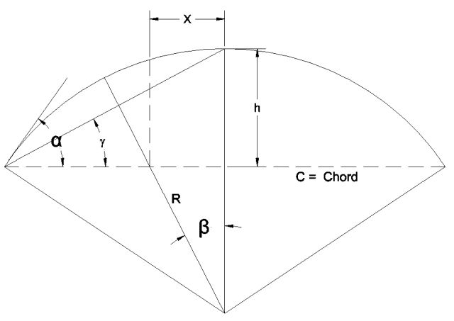
Figure 28 – Unbalanced Snow Load for Curved Roof

![]()
ÃŽ² < 30° ( Case 1)  Ò Ã’ 30° < ÃŽ² < 70° (Case 2)  Î² > 70° (Case 3)
ÃŽ± > 70° = PR = 0
ÃŽ³ ????âžÅ½Ã°˜”????âžÅ½ ???????? ????ð˜â”¢Ã°˜Å”????????ð˜Å”???? ????????ð˜Å¸Ã°˜Å½Ã°˜”????h???? ð˜â”¢Ã°˜”????????????ð˜Å¸Ã°˜Å”ð˜Å¡ 70° ???????? ÃŽ³ < 10° ð˜Å”ð˜Å¸ ÃŽ³ > 60° ð˜Æ’???? = 0

Figure 29 – Balanced and Unbalanced Loads Dependent on the Slope at Eaves
I. Unbalanced Snow Load For Dome Roof
Unbalanced snow loads shall be applied to domes and similar rounded structures. Snow loads, determined in the same manner as for curved roofs in Section 7.6.2, shall be applied to the downwind 90° sector in plan view. At both edges of this sector, the load shall decrease linearly to zero over sectors of 22.5° each. There shall be no snow load on the remaining 225° upwind sector.

Figure 30 – Unbalanced Snow Load for Dome Roof
J. Unbalanced Snow Loads for Multiple Folded Plate, Sawtooth, and Barrel Vault Roofs

Figure 31 – Balanced and Unbalanced Loads on a Sawtooth Roof
Apply if slope exceeds 3/8 in. / ft Cs = 1.0 Balanced snow load equals pf.
The unbalanced snow load shall increase from 0.5pf at the ridge or crown to 2Pf/Ce
the snow surface above the valley shall not be at an elevation higher than the snow above the ridge.

6.5.6. DRIFT

Figure 32 – Drifts Formed and Windward and Leeward Steps

Figure 33 – Configuration of Snow Drifts on Lower Roofs
ÃŽ³S = 0.13pg + 14 < 30 pcf)
hb = pf/s/ÃŽ³s  hc = hParap – hb
if hc/hb < 0.2 â No Drift
Pd = hd ÃŽ³s
If lu < 20 ft, use lu = 20ft
hd = 0.43 ∺lu ∜pg+10 – 15 See Below for the hd Values
For Leeward Drift  lu – Upper Roof  Ò Ã’ hd_Leeward = hd Factor 1.0
For Windward Drift lu = Lower Roof  hd_Windward = 0.75hd Factor 0.75
Pd_MAX = Max (hd_Leeward , hd_Windward) ÃŽ³s

Figure 34
![]()
If W > lu â Truncate the Load
6.5.7. ADJACENT BUILDING
For Leeward:
hd = { if S < 20 and S â°¥ 6H â¡ No Drift hd = 0 if S < 20 and S < 6H â¡ hd = (hd , 6hâˆS / 6)
W = (6hd , (6h – S)

Figure 35
Windward:
Calculate hd per Section 18.5 but it shall be truncated per the above sketch.

Figure 36
![]()
6.5.8. SNOW SLIDING
Case I: Attached Lower Roof
The Sliding shall be considered if the slope of the main roof is greater than 0.25/12 for slippery and 2/12 for non-slippery roof. For slopes less than the criteria, no sliding snow load is required.
Condition: The Sliding Snow load will be uniformly distributed on 15ft. So, if the lower roof is smaller than 15ft, the load shall be truncated.
![]()
Case II: For a roof adjacent to the main roof
![]()
If S > 15 No Sliding Snow

Figure 37
Need NOT to add Sliding Snow to Drift or Unbalanced ” Superimposed on Balanced ONLY.
6.5.9. ROOF PARTITIONS (ROOF TOP (RTU)) AND PARAPETS
For Parapet: L = lu (Windward)
For Parapet, hd = 0.75 hd
hd = 0.75 (0.43 ∺lu · ∜pg+10 – 1.5 (See also Table but use ¾ hd)
For Projections: L = lu = max ( l1, l2 ) less than 15ft (No Drift is required) hd = 0.75 hd
hd = 0.75 (0.43 ∺lu ∜pg+10 – 1.5 (See also Table but use ¾ hd)

Figure 38
6.5.10. RAIN ON SNOW
if Pg < 20psf and Slope < W/50 â Prain = 5psf surcharged load to sloped roof balanced
Need NOT to add rain snow to Drift, Unbalanced, Sliding, Minimum Snow Load.
6.6. RAIN LOAD
Q = 0.0104 A. i
A = roof area serviced by a single drainage system, in ft2 (m2)
i = design rainfall intensity as specified by the code having jurisdiction, in./h (mm/h)
Q = flow rate out of a single drainage system, in gal/min (m3/s)
Rain Load: R = 5.2 (ds + dh)
Select type of secondary drain and plug the Q into table and find the dh , ds will be given.

Figure 39 – Hydraulic Head for Rain Load (dh) [Table C8-1]

Figure 40
6.7 ICE LOAD
Wice = Vi Ô Yice
Yice â°¥ 56pcf
Vi = π Ô td Ô Ai
Ai = π Ô td Ô (Dc + td)
For Flat Plate Ai_Dome_Sphere = π Ô r2)

Table 21 ” Ice Equivalent Diameter ( Dc ) – Click to open the open source spreadsheet in a new tab
td = 2.0 Ô t Ô Ii Ô fz Ô Kzt0.35
 - Click to open the open source spreadsheet in a new tab")
Table 22 – Click to open the open source spreadsheet in a new tab
Kzt : ASCE 7 – 10 Chapter 26 (Wind)
Content coming…
fz = {(Z/33)0.1 if 0 < Z < 900ft 1.4 Â if Z > 900 ft

Figure 41 – Ice Thickness in Eastern Half of the US
t = ASCE7 – 10 Figure 10 – 2 to 10 – 5
6.8. SEISMIC DESIGN CRITERIA
6.8.1. SEISMIC GROUND MOTION VALUES
The Parameter SS and S1 will be obtained by Map (Fig. 22-1 to 22-5) or USGS website.
6.8.2. SITE CLASS
Site Class depends on soil properties. Based on the site soil properties, the site shall be classified as Site Class A, B, C, D, E, or F in accordance with Chapter 20.
Consider Site Class “D” (Default) when soil properties are not defined unless the authority having jurisdiction or geotechnical data determines Site Class E or F soils are present at the site.
6.8.3. AVERAGE SHEER WAVE VELOCITY
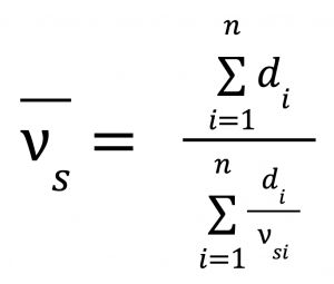
di : Thickness of any layer between 0 and 100 ft
vsi : The shear wave velocity ft / s
![]()
A. Average Field Standard Penetration Resistance N
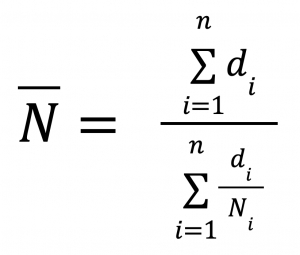
Ni : Standard Penetration Resistance (SPR for SPT)
not to exceed 100 blows/ft for Cohesionless, Cohesive, and Rock Layers
B. Average Field Standard Penetration Resistance for Cohesionless Soil Layer Nch
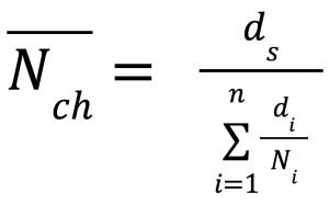
Ni : Standard Penetration Resistance (SPR for SPT) not to exceed 100 blows/ft,
For Rock Layer, Ni Shall be taken as 100 blows/ft
![]()
ds: Total thickness of cohesionless soil layers in the top 100ft

Table 23 ” Soil Shear Wave Velocity ( Vs ) – Click to open the spreadsheet in a new tab
6.8.4 SITE COEFFICIENT AND RISK-TARGETED
Maximum Considered Earthquake (MCE) Spectral Response Acceleration Parameters
Fa , Fv…………..Site Coefficient

Figure 42 – Site Coefficient, Fa [Table 11.4-1]

Figure 43 – Site Coefficient, Fv [Table 11.4-2]
SMS = Fa · Ss  Ò Ã’ Ã’ Ã’ Ã’ Ã’ Ã’ SM1 = Fv · S1
The two values provided Ss and S1, represent the risk targeted maximum considered earthquake (MCE) response accelerations at a period of 0.2 second, and 1.0 second for site class B soil profile and 5-percent damping. Periods of 0.2 second and 1.0 seconds represent the approximate natural period of short and tall building, respectively.
Design Earthquake is two-third (2/3) of the corresponding maxim um considered earthquake effect.
Design Earthquake Ground Motion is two-third (2/3) of the corresponding maximum considered earthquake.
6.8.5. DESIGN SPECTRAL ACCELERATION PARAMETERS SDS, SD1
SDS = 2/3 SMS Â Ã’ Ã’ Ã’ Ã’ SD1 = 2/3 SM1
Sa = SDS (0.4 + 0.6 T/T0)
Sa = SD1 / T Â Ã’ Ã’ Ã’ Ã’ Ã’ Sa = (SD1 Ô TL) / T2
T = Fundamental Period of the Structure
TL = Fig. 22 – 16 (ASCE7 – 10)
T0 = 0.2Ts = 0.2 SD1/SDS Ts = SD1/SDS

Figure 44 – Spectral Response Acceleration vs Period Graph
6.8.6. SEISMIC DESIGN CATEGORY
 - Click to open the open source spreadsheet in a new tab")
Table 24 ” Seismic Category (SDS SD1) – Click to open the spreadsheet in a new tab
6.8.7. GEOHAZARD AND GEOTECHNICAL INVESTIGATION
- Site E and F – It is not allowed to build a structure in the Site Category E and F if an active fault exists.
- Geotechnical Investigation – The geotechnical report for site class C, D, E, and F shall be provided to show the following:
- Slope Instability
- Liquefactions
- Total and Differential settlement
- Surface Displacement due to faulting or seismically induced lateral separation or lateral flow
- Exception: Not required by prior approval of authority with considering the prior evaluation of nearby sites with similar soil conditions
- Additional Information for Geotechnical Investigation for Site D, E, and F
- The determination of dynamic seismic lateral earth pressures on basement and retaining walls due to design earthquake ground motions
- The potential for liquefaction and soil strength loss is evaluated for site peak ground acceleration, earthquake magnitude, and source characteristics consistent with the MCEG peak ground acceleration
- Peak ground acceleration shall be determined based on either
- A site-specific study taking into account soil amplification effects (§11.4.7)
- The peak ground acceleration PGAM
PGAM = FPGA • PGS (Peak Ground Acceleration)

Figure 45 – Site Coefficient (FPGA ) [Table 11.8-1]
6.8.8. SEISMIC DESIGN REQUIREMENTS FOR BUILDING STRUCTURES
6.8.8.1. Minimum Seismic Force for Separate Joint
FE_min_SJ = (0.133 SDS , 0.05) Ô weight of connection portion
6.8.8.2. Minimum Seismic Force for Connection to Support
FE_min_Conn = 0.05 Ô (D + L)
6.8.8.3. Combination of Framing system in the Same Direction ” Vertical Combination
Where different seismic force-resisting systems are used in combination to resist seismic forces in the same direction other than those combinations considered as dual systems, the most stringent applicable structural system limitations contained in Table 12.2-1 shall apply and the design shall comply with the requirements of this section.
D. Vertical Combination
{If Rupper > Rlower â¡ {For Upper Portion – Use Upper R for Force and Drift and Force
For Lower Portion – Use Lower R for Drift and force shall be adjusted by
 / (R lower / p lower)")
If Rupper < Rlower â¡ Use Upper System for the entire building

Figure 46
Exception:
- Rooftop Structures not exceeding two (2) stories in height and 10% of total structure weight.
- Other supported structural systems with a weight equal to or less than 10% of the weight of the structure.
- Detached one- and two-family dwellings of light-frame construction.
6.8.8.4. Two-Stage Analysis Procedure
When upper portion is flexible compare to lower portion:
- The stiffness of lower portion shall be 10 times the stiffness of upper portion.
- The period of the entire structure shall not be greater than 1.1 times the period of the upper portion.
- The upper portion shall be designed as a separate structure using the appropriate values of R and ρ.
- The lower portion shall be designed as a separate structure using the appropriate values of R and ρ. The reactions from the upper portion shall be those determined from the analysis of the upper portion amplified by the ratio of the R/ρ of the upper portion over R/ρ of the lower portion. This ratio shall not be less than 1.0.
- The upper portion is analyzed with the equivalent lateral force or modal response spectrum procedure, and the lower portion is analyzed with the equivalent lateral force procedure.
6.8.8.5. Combination of Framing system in the Same Direction ” Horizontal Combination
R, Cd , ÃŽ©req = (R, Cd , ÃŽ©)
Exception:
Resisting elements are permitted to be designed using the least value of R for the different structural systems found in each independent line of resistance if the following:
- Risk Category I or II building
- Two stories or less above grade plane, and
- Use of light-frame construction or flexible diaphragms. The value of R used for design of diaphragms in such structures shall not be greater than the least value of R for any of the systems utilized in that same direction.

Figure 47
6.8.8.6. Combination Framing Detailing Requirements
Structural members common to different framing systems used to resist seismic forces in any direction shall be designed using the detailing requirements from ASCE 7-16 of Chapter 12 required by the highest response modification coefficient, R, of the connected framing systems.
6.8.8.7. Resisting System-Specific Requirements
A. Dual System
For a dual system, the moment frames shall be capable of resisting at least 25% of the design seismic forces. The total seismic force resistance is to be provided by the combination of the moment frames and the shear walls or braced frames in proportion to their rigidities.
B. Cantilever Column System
Cantilever column systems are permitted as indicated in Table 12.2-1 and as follows:
- The required axial strength of individual cantilever column elements, considering only the load combinations that include seismic load effects, shall not exceed 15% of the available axial strength, including slenderness effects.
- Foundation and other elements used to provide overturning resistance at the base of cantilever column elements (Foundation/Base Plate) shall be designed to resist the seismic load effects including overstrength factor (ÃŽo) of Section 12.4.3.
C. Increased Structural Height Limit
For Steel Eccentrically, Braced Frames, Steel Special Concentrically Braced, Frames, Steel Buckling-Restrained Braced Frames, Steel Special Plate Shear Walls, and Special Reinforced cast in-place Concrete Shear Walls.
- For Category D, E increase from 160ft to 240ft.
- For Category F, increase from 100ft to 160ft.
IF:
- No extreme torsional irregularity (horizontal structural irregularity Type 1b).
- 60% of total forces shall be resisted by the resisting system mentioned above for each direction.
D. Steel Ordinary Moment Frame
For Seismic Design Category D, E:
- Maximum height of 65ft, if where the dead load supported by and tributary to the roof does not exceed 20 psf. In addition, the dead load of the exterior walls more than 35 ft (10.6 m) above the base tributary to the moment frames shall not exceed 20 psf.
- Enclose equipment or machinery/maintenance/monitoring of that equipment, permitted to be of unlimited height where the sum of the dead and equipment loads supported by and tributary to the roof does not exceed 20 psf. Dead load of the exterior wall system including exterior columns more than 35 ft above the base shall not exceed 20 psf. See 12.2.5.6.1 exception for additional info.
- Steel ordinary moment frames not meeting the limitations above are permitted within light-frame construction up to a structural height of 35 ft where neither the roof dead load nor the dead load of any floor above the base supported by and tributary to the moment frames exceeds 35 psf. In addition, the dead load of the exterior walls tributary to the moment frames shall not exceed 20 psf.
For Seismic Design Category F:
- Single-story steel ordinary moment frames permitted up to a structural height of 65 ft where the dead load supported by and tributary to the roof does not exceed 20 psf. In addition, the dead load of the exterior walls tributary to the moment frames shall not exceed 20 psf.
E. Steel Intermediate Moment Frame
For Seismic Design Category D:
- 35ft is allowed for all building.
- Single-story permitted up to height of 65 ft (20 m) where the dead load supported by and tributary to the roof does not exceed 20 psf. Dead load of the exterior walls more than 35 ft above the base tributary to the moment frames shall not exceed 20 psf.
- Enclose equipment or machinery/maintenance/monitoring of that equipment, permitted to be of unlimited height where the sum of the dead and equipment loads supported by and tributary to the roof does not exceed 20 psf. Dead load of the exterior wall system including exterior columns more than 35 ft above the base shall not exceed 20 psf. See 12.2.5.6.1 exception for additional info.
For Seismic Design Category E:
- Single-story steel permitted up to height of 65 ft where the dead load supported by and tributary to the roof does not exceed 20 psf. Dead load of the exterior walls more than 35 ft above the base tributary to the moment frames shall not exceed 20 psf.
- Enclose equipment or machinery/maintenance/monitoring of that equipment, permitted to be of unlimited height where the sum of the dead and equipment loads supported by and tributary to the roof does not exceed 20 psf. Dead load of the exterior wall system including exterior columns more than 35 ft above the base shall not exceed 20 psf. See 12.2.5.6.1 exception for additional info.
- If does not meet the criteria 1, and 2 above, permitted up to height of 35 ft where neither the roof dead load nor the dead load of any floor above the base supported by and tributary to the moment frames exceeds 35 psf. Dead load of the exterior walls tributary to the moment frames shall not exceed 20 psf.
For Seismic Design Category F:
- Single-story permitted up to height of 65 ft where the dead load supported by and tributary to the roof does not exceed 20 psf. Dead load of the exterior walls tributary to the moment frames shall not exceed 20 psf.
- Not meeting 1, permitted within light frame construction up to height of 35 ft where neither the roof dead load nor the dead load of any floor above the base supported by and tributary to the moment frames exceeds 35 psf. Dead load of the exterior walls tributary to the moment frames shall not exceed 20 psf.
F. Steel Special Moment Frame
A special moment frame that is used but not required by Table 12.2-1 is permitted to be discontinued above the base and supported by a more rigid system with a lower response modification coefficient, R. See 22.3.
G. Shear Wall-Frame Interaction System
The shear strength of the shear walls of the shear wall-frame interactive system shall be at each story. The frames of the shear wall-frame interactive system shall be capable of resisting at least 25% of the design story shear in every story.
6.8.8.8. Flexible Diaphragm Condition

Figure 48 – Flexible Diaphragm [Figure 12.3-1]

Figure 49
Steel decking or wood structural panels are flexible if any of the following conditions exist:
- In structures where the vertical elements are steel braced frames; steel and concrete composite braced frames; or concrete, masonry, steel, or steel and concrete composite shear walls.
- In one- and two-family dwellings.
In structures of light-frame construction where all of the following conditions are met:
- Topping of concrete or similar materials is not placed over wood structural panel diaphragms except for nonstructural topping no greater than 1 1/2 in. thick.
- Each line of vertical elements of the seismic force resisting system complies with the allowable story drift of Table 12.12-1.
6.8.8.9. Rigid Diaphragm
Concrete slabs or concrete-filled metal deck with span-to-depth ratios of 3 or less in structures that have no horizontal irregularities are permitted to be idealized as rigid.
6.8.8.10. Rigid Diaphragm Analysis
The diaphragm contains two major centers:
- Center of Mass (CM)
- Center of Rigidity (CR)
In any circumstances, two major torsion can occur based on the position of the CM and CR:
- 1- Inherent Torsion
- Depend on the actual location of CM and CR, inherent torsion occurs
- 2- Accidental torsion
- In all, considering the eccentricity between CM and CR will be increased by 5% of the length of the building in the direction of perpendicular to the applied seismic force.
 Center of Rigidity (CR) - Inherent Torsion, Accidental torsion")
Figure 50
If type 1a and 1b Horizontal (Torsional) Irregularity, the accidental torsion shall be amplified by a factor of
![]()
Distribution of Shear and Torsion to Seismic Force Resisting Members

X-Direction
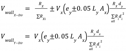
Y-Direction
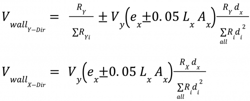
![]()
6.8.8.11. Irregular and Regular Classifications
A. Horizontal Irregularities

Table 25A – Horizontal Irregularity – Click to open the spreadsheet in a new tab

Table 25B – Horizontal Irregularity – Click to open the spreadsheet in a new tab
B. Vertical Irregularities

Table 26A – Vertical Irregularity – Click to open the spreadsheet in a new tab

Table 26B – Click to open the spreadsheet in a new tab
6.8.8.12. Redundancy Factor
A. Redundancy factor ρ = 1.0
ρ = 1.3 but ρ = 1.0 will be apply to the following:
- SDC B, C
- Drift Calculation and P-Delta Effect
- Non-Building Structure NOT Similar to Building
- Non-Structural Elements/components
- Collector, Splice, and their connections since they will be design for ÃŽ©o
- If ÃŽ©o is considered
- Diaphragm Load Fp
- Design Out-of-Plane forces for the Structural wall ” Including their anchorage
B. Redundancy factor for SDC D, E, F
Except Extreme Torsional irregularity, the ρ = 1.3 can be considered as ρ = 1.0 if:
- Each Story resist 35% of the base shear
- Structure with regular plan at all levels consist of:
- Minimum two (2) bays of seismic resisting force at each side at each orthogonal direction

Table 27 ” Redundancy Factor (ρ) – Click to open the spreadsheet in a new tab

Figure 51

Figure 52
6.8.8.13. Equivalent Lateral Force
V = Cs Ô Weff
![]()
![]()
![]()
C. Seismic Effective Weight
According to ASCE7-10 §12.7.2 Weff, the effective seismic weight is:
- Dead Load
- 25% of Live Load of Storage Area
- Exception:
- If the storage loads added no more than 5% to the effective seismic weight, it is not required to be considered
- Floor live load in public garage and open parking structure
- Actual partition weight not less than 10psf
- 20% of uniform design snow load when flat snow load exceeds 30psf (regardless of actual roof slope)
- Weight of Landscape and other material at roof garden and similar area
- Exception:
D. Fundamental Period of Structure
Per section 12.8.2 of ASCE, the period of structure shall be calculated per a substantiated method. The Rayleigh method is commonly used to determine the period of the structure

ÃŽ´i : Static elastic deflection @ level i
fi : Lateral Force @ level i
wi : Seismic weight @ level i
g: gravity acceleration 32.2ft / s2 or 386.4 in / s2
E. Approximate Fundamental Period of Structure
Method A: applicable for all structures
Ta = Ct Ô hnx
hn = Total height of Structure (ft)
From base to the highest level of resisting system (excluding parapet)

Table 28 ” Ct and x values for App. Fundamental Period of structures – Click to open the spreadsheet
Method B: applicable for Steel or Concrete Moment Resisting Frame not more than 12 stories above the base and average story height of 10ft minimum
Ta = 0.1 N
N:Number of Stories
Method C: applicable for Masonry or Concrete Shear Walls less than 120ft tall:
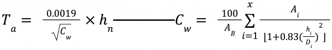
-AB = Area of Base
Ai = Web area of Shear Walls
hi = height of Shear Wall Di = Length of Shear Walls
X = Number of shear walls in the building effective
F. Upper Limit Fundamental Period of Structure
The calculated period of structure by rational method (Modal Analysis) shall not exceed the following upper limit:
Tr = Cu Ô Ta
Ta: Approximate Period (See Above)

Table 29 ” Cu Upper Limit Fundamental Period of structures – Click to open the spreadsheet
6.8.8.14 Seismic Force in SCS “A”
V = Fx = 0.01W
V = Base Shear
Fx = Force @ Each Level
W = Total Dead Load
6.8.8.15. Vertical Distribution of Seismic Force
If shall be noted, the seismic force at each level is NOT Diaphragm force
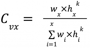
Fx = Cvx Ô V

Figure 53
k = {1  Ò if T Ⱔ 0.5 sec 0.75 + 0.5T  Ò if  0.5sec < T < 2.5 sec 2  Ò if.  Ò T Ⱕ 2.5 sec
6.8.8.16. Overturning
When:
a) The Structures is designed by the Equivalent Lateral Force and,
b) The Structure is not cantilever column system,
The overturning moment may be reduced by 25% => Mo = Mo Ô 0.25
When modal response spectrum is considered:
The overturning moment may be reduced by 10% => Mo = Mo Ô 0.10
6.8.8.17. Retaining Wall Overturning and Sliding Safety Factor [Ref. IBC §1807.2]
ASD Load Combination with no Seismic SF=1.5 for sliding and overturning
ASD Load Combination with Seismic load (0.7 factor) SF=1.1 for sliding and overturning
Factor 1.0 times other nominal loads
6.8.8.18. Story Drift Determination
ÃŽ´x = Cd Ô ÃŽ´xe / Ie
ÃŽ´x = Amplified Deflection
ÃŽ´xe = Elastic Deflection

Figure 54 – Story Drift Determination [Figure 12.8-2]
ÃŽ1 = ÃŽ´1
ÃŽ2 = (ÃŽ´xe2-ÃŽ´xe1) Ô Cd / Ie

Figure 55 – Allowable Story Drift [Ref. ASCE 7-10 Table 12.12.1]
For Only moment frame in SDC D, E, F ÃŽa = ÃŽa/ρ
6.8.8.19. ρ – ÃŽ Effect

Px = D + L (No Factor)
If ÃŽ¸ â°¤ 0.1 P – ÃŽ can be neglected
ÃŽ¸ Shall not exceed ÃŽ¸max = 0.5/ÃŽ²Cd â°¤ 0.25
ÃŽ² = Shear Demand / Shear Capacity Conservatively use ÃŽ² = 1.0
If 0.1 < ÃŽ¸ â°¤ ÃŽ¸max Two methods can be considered for amplification of force:
- Analytical (Rational) Analysis considering the deformed shape,
and ÃŽ¸ /(1 + ÃŽ¸) â°¤ ÃŽ¸max shall be satisfied - Increase the load by the factor of 1/(1-ÃŽ¸)
If ÃŽ¸ > ÃŽ¸max Re – design the Structure
6.8.8.20. Structural Separation
![]()
Where ÃŽ´M1 and 2 = maximum inelastic displacement at the same height

Figure 56
6.8.8.21. Directional Load Combination
Content coming…
6.8.8.22. Limitation of Equivalent Lateral Force Analysis (ELFA)
Content Coming…
6.8.8.23. Diaphragm Loading
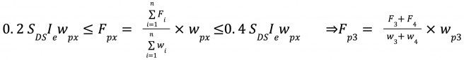

Figure 57
6.8.8.24. Out”of-Plane Seismic Force for Walls
0.1 wwall Ⱔ Fpx = 0.4 SDS Ie wwall (Ô0.7 ASD)
6.8.8.25. Anchorage for Walls
0.2 ka SDS Ie wwall (Ô0.7 AsD) Ⱔ Fpx = 0.4 ka SDS Ie wwall (Ô0.7 AsD)
ka = 1.0 Rigid Diaphragm
ka = 1 + Lf / 100
Lf = Length between Lateral Resisting Elements (shear walls) in the direction of seismic load
Exception:
If the diaphragms are not flexible and the and anchorage is not installed at the roof level, the out-of-plane force provided above can be reduced by a factor of:
![]()
Note:
If the spacing of anchors exceeds 4ft, the wall shall be designed for bending between anchors.
No ρ or ÃŽ©o is required to be considered.
6.8.8.26. Simplified Seismic Analysis Procedure
For small bearing wall or building frame-type structures, classified as Risk Category I or II and not exceeding three stories in height the following can be considered (ASCE 7-10 Sec. 12.14):
![]()
F = 1.0 for buildings that are one story above grade plane
F = 1.1 for buildings that are two stories above grade plane
F = 1.2 for buildings that are three stories above grade plane
R = the response modification factor from Table 12.14-1
W = effective seismic weight:
- Dead Load
- 2- 25% of Live Load of Storage Area
- Exception:
- a) If the storage loads added no more than 5% to the effective seismic weight, it is not required to be considered
- b) Floor live load in public garage and open parking structure
- Exception:
- Actual partition weight not less than 10psf
- 20% of uniform design snow load when flat snow load exceeds 30psf (regardless of actual roof slope)
- Weight of Landscape and other material at roof garden and similar area
- Total operating weight of permanent equipment

If this procedure is used, the overturning effects for foundation shall be calculated for 75% of foundation overturning design moment. The ratio is 0.75 instead of 1.0.
Drift Limits and Building Separation need not be calculated. For other purposes 1% of height of structure (hn).
6.8.9. SEISMIC DESIGN REQUIREMENTS FOR NONSTRUCTURAL COMPONENTS
6.8.9.1. Application
This section does not apply to:
- Furniture
- Architectural Components in SDC B Except Parapet Wall (I = 1.0)
- Mechanical and Electrical Components in SDC B
- Mechanical and Electrical Components in SDC C if I = 1.0
Mechanical and Electrical Components in SDC D, E, F if all following apply:
- I = 1.0
- Component positively attached to the structure
Flexible connections are provided between components and associated ductworks, piping, conduit, and either:
- Component weight 400lb or less and has center of mass 4ft above level
- Component weight 20lb or less or, in case of a distribution system

Figure 58 – Exemptions to Seismic Design Requirements [Table 1-24]
6.8.9.2. Importance Factor
I – 1.5 for
- Life Safety Components
- Toxic, explosive Components
- Attached to Cat. IV structures
- Hazardous substances Components
6.8.9.3. Special Certification Requirements for Designated Seismic System
ICC-ES AC 156 – Seismic Certification by Shake-table Testing of Nonstructural Components
6.8.9.4. Seismic Demand on Nonstructural Components
A. Horizontal Seismic
![]()

Figure 59 – 1 for Rp and ap [Figure 13.5]
B. Vertical Seismic
Fp_Verticle = ± 0.2 SDSWp
Vertical Seismic is exempt for lay – in access floor panel and lay – in ceiling panels
ρ = 1.0 and Ω = does not apply except anchorage to concrete
6.8.9.5. Seismic Demand on Nonstructural Components (Modal Analysis)
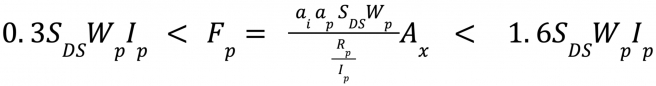
ai = Acceleration @ level i per Modal Analysis
Ax = (ÃŽ´max/1.2ÃŽ´avg)2 Section 12.8.4.2 Eq. 12.8-14
6.8.9.6. Seismic Relative Displacement
A. Displacement within the Structure
Dp = ÃŽ´xA ∠δyA

Figure 60
Alternative method based on Modal Analysis:
![]()
ÃŽaA : Allowable Story Drift for Structure “A”
Table 12.12-1 (Figure 55)
B. Displacement Between Structure
The Dp shall not be more than:
![]()

Figure 61
ÃŽaA or B:Allowable Story Drift for Structure “A or B” Table 12.12.-1 (Figure 55)
No Friction Clip is allowed for Seismic Design category D, E, or F
6.8.9.7 Glass
ÃŽfallout â°¥ 1.25 IeDp
ÃŽfallout : relative seismic displacement (Drift) by analysis or AAM 501.6
Exception: If the Glass has clear spacing from its frame
Dclear â°¥ 1.25 Dp
Dclear = 2c1 ( 1 + hpc2 / bpc1 )
hp = the height of the rectangular glass panel
bp = the width of the rectangular glass panel
c1 = the average of the clearances (gaps) on both sides between the vertical glass edges and the frame
c2 = the average of the clearances (gaps) top and bottom between the horizontal glass edges and the frame
6.8.10. BUILDING LATERAL RESISTING SYSTEM
Moment Frame both directions with HSS tube sections

Figure 62 – Diaphragm Connection to RHS column: (a)external (b) through

Figure 63 – Lifting Trucks/Devices
Consider the machine below as the high end for allowable size:

Figure 64 – Lift Truck Used for Steel Structure

Figure 65
California = 0
Utah = 20psf
Wind

Figure 66

Table 30A – Click to open the open source spreadsheet in a new tab

Table 30B – Click to open the open source spreadsheet in s new tab

Table 30C – Click to open the open source spreadsheet in a new tab

Table 30D – Click to open the open source spreadsheet in a new tab

Table 30E – Click to open the open source spreadsheet in a new tab

Table 30F – Click to open the open source spreadsheet in a new tab

Table 30G – Click to open the open source spreadsheet in a new tab
California: 110 mph
Utah: 112 mph

Figure 67 – Map of Utah Counties

Table 31A – Click to open the open source spreadsheet in a new tab

Table 31B – Click to open the open source spreadsheet in a new tab

Table 31C – Click to open the open source spreadsheet in a new tab
7. CIVIL DESIGN SPECIFICATIONS
Content coming…
8. MECHANICAL DESIGN SPECIFICATIONS
Content coming…
9. PLUMBING DESIGN SPECIFICATIONS
Chapter 29 of CBC code – PLUMBING SYSTEMS

Figure 68 – Minimum Number of Required Plumbing Fixtures [Table 2902.1] Figure 69 – Minimum Number of Required Plumbing Fixtures (continued)

Figure 70 – Minimum Number of Required Plumbing Fixtures (continued part 2)
MIN Number of Required Plumbing Fixtures Calculation
Table 32 – Click to open the open source spreadsheet in a new tab

Table 33 – Minimum Number of Required Plumbing Fixtures Calculated: First Floor – Click to open the spreadsheet

Table 34 – Click to open the open source spreadsheet in a new tab
Table 35 – Click to open the open source spreadsheet in a new tab
2902.3.3 Location of toilet facilities in occupancies other than malls. In occupancies other than covered and open mall buildings, the required public and employee toilet facilities shall be located not more than one story above or below the space required to be provided with toilet facilities, and the path of travel to such facilities shall not exceed a distance of 500 feet (152 m).
2902.6 Small occupancies. Drinking fountains shall not be required for an occupant load of 15 or fewer.
10. ELECTRICAL DESIGN SPECIFICATIONS
Content coming…
11. INSTRUMENTATION DESIGN SPECIFICATIONS
Content coming…
12.PLANNING
Content coming…
13. CONSTRUCTION
Content coming…
14.INSPECTION
Content coming…
15. WATER–BASED FIRE SUPPRESSION SYSTEMS
15.1 FIRE & LIFE SAFETY SYSTEMS
15.1.1. SUMMARY
A. This section includes fire-suppression equipment for Wet pipe sprinkler systems.
B. This section includes:
1. Pipes, fittings and specialities.
2. Fire protection valves.
3. Speciality valves.
4. Backflow preventer.
5. Fire department connections.
6. Sprinklers.
7. Alarm devices.
8. Manual control stations.
9. Pressure gauges.
C. Related Requirements:
1. Refer to FP Series Drawings for additional requirements.
2. Section XX for “Fire Extinguisher Cabinets”and “Fire Extinguishers” for cabinets and fire extinguishers.
15.1.2. DEFINITIONS
A. CR: Chlorosulfonated polyethylene synthetic rubber.
B. FMG: Factory Mutual Global.
C. PE: Polyethylene plastic.
D. Underground Service-Entrance Piping: Underground service piping below the building.
15.1.3. SYSTEM DESCRIPTIONS
A. Wet-Pipe Sprinkler System: Automatic sprinklers are attached to piping containing water and that is connected to water supply. Water discharges immediately from sprinklers when they are opened. Sprinklers open when heat melts fusible links or destroys fragile devices. Hose connections are included if indicated.
15.1.4. PERFORMANCE REQUIREMENTS
A. Standard Piping System Component Working pressure: Listed for at least 175 PSIG minimum working pressure.
B. Fire-suppression sprinkler system design shall be approved by authorities having jurisdiction.
1. Margin of safety for available water flow and pressure: 10 percent or 10 PSI, whichever is greater, including losses through water-service piping, valves, and backflow preventers. Unless noted otherwise, the safety margin shall be determined based on the hydraulic demand of each remote area.
2. Refer to FPXXX series drawings for sprinkler occupancy hazard classifications, minimum density for automatic-sprinkler piping design, and maximum protection area per sprinkler.
3. Where sprinkler system occupancy hazard classifications, minimum design density, and/or maximum protection area per sprinkler are not noted on contract drawings, they shall be in accordance with NFPA13, FM data sheet guidelines, and/or UL listings for equipment.
C. Seismic Performance: Sprinkler piping shall withstand the effects of earthquake motions determined according to NFPA 13 when required by the building code and ASCE/SEI 7.
15.1.5. SUBMITTALS
A. Product Data: For each type of product, including rated capacities, operating characteristics, electrical characteristics, and furnished specialities and accessories, for the following:
1. Piping materials, including dielectric fittings, and sprinkler speciality fittings.
2. Pipe hangers and supports, including seismic restraints.
3. Valves, including listed fire-protection valves, unlisted general-duty valves, and speciality valves and trim.
4. Sprinklers, escutcheons, and guards. Include sprinkler flow characteristics, mounting, finish and other pertinent data.
5. Fire department connections, including type; number, size and arrangement of inlets; caps and chains; size and direction of outlet; escutcheon marking ; and finish.
6. Alarm devices, including electrical data.
B. Water Supply Data: Fire protection contractor shall arrange and conduct a waterflow test in accordance with the procedures of the local authority, prior to the preparation of hydraulic calculations. If a previous flow test or pump test results are used, the test must be within 12 months prior to shop drawing submission, in accordance with NFPA 13. Submit a copy of the test results for review/record.
C. Shop Drawings: Working plans prepared according to NFPA 13, that have been approved by authorities having jurisdiction, including hydraulic calculations for each zone, as applicable.
1. Include plans, elevations, sections and attachment details.
2. Include diagram power, signal, and control wiring3. Sprinkler systems, drawn to scale, on which the following items are shown and coordinated with each other, using input from installers of the items involved:
a. Piping, including domestic water and compressed air.
b. Mechanical ductwork, piping, and associated equipment.
c. Electrical conduits, equipment, and lighting.
d. Structural systems.
e. Cold.
D. Include locations of items for coordination, including inspector’s test connections and drain valves.
E. For shop drawings submitted in multiple sections, submit a full set of working drawings for information after approval of all sections.
F. Field Test Reports and Certificates: Indicate and interpret test results for compliance with performance requirements as described in NFPA 13. Include “Contractor’s Material and Test Certificate for Aboveground Piping” and Contractor’s Material and Test Certificate for Underground Piping.”
16. DIGITAL ADDRESSABLE FIRE ALARM SYSTEM
16.1. SYSTEM DESCRIPTION
A. Non-coded, addressable system; multiplexed signal transmission dedicated to fire alarm service only.
16.2. PERFORMANCE REQUIREMENTS
A. Comply with NFPA 72.
B. Fire alarm signal initiation shall be by one or more of the following devices, as indicated:
1. Manual stations.
2. Heat detectors.
3. Spot-type smoke detectors.
4. Automatic sprinkler system water flow (water pressure switch or flow switch).
C. Fire alarm signal shall initiate the following actions:
1. Alarm notification appliances shall operate continuously.
2. Identify alarms at the FACP and remote annunciators.
3. De-energize electromagnetic door holders.
4. Transmit an alarm signal to the remote alarm receiving station.
5. Unlock electric door locks in designated egress paths.
6. Release fire and smoke doors held open by magnetic door holders.
7. Switch heating, ventilating, and air-conditioning equipment controls to fire alarm mode.
8. Close smoke dampers in air ducts of the system serving zone where the alarm was initiated.
9. Record events in the system memory.
D. Supervisory signal initiation shall be by one or more of the following devices or actions:
1. Operation of a fire-protection system valve tamper switch.
2. Duct smoke detectors.
3. Supervisory signal-initiating devices on early warning detection systems.
4. Supervisory bypass for pre-action sprinkler zone, fire smoke dampers, air sampling smoke detection, and air handling equipment smoke shutdown.
E. System trouble signal initiation shall be by one or more of the following devices or actions:
1. Open circuits, shorts and grounds of wiring for initiating device, signaling line, and
notification-appliance circuits.
2. Opening, tampering, or removal of alarm-initiating and supervisory signal-initiating devices.
3. Loss of primary power at the FACP.
4. Ground or a single break in FACP internal circuits.
5. Abnormal ac voltage at the FACP.
6. A break in standby battery circuitry.
7. Failure of battery charging.
8. Abnormal position of any switch at the FACP or annunciator.
9. Abnormal position of any manual bypass switch.
10. Trouble condition indicated at any air-sampling smoke detector.
11. Low-air-pressure switch operation on a dry-pipe or pre-action sprinkler system.
F. System Trouble and Supervisory Signal Actions: Ring trouble bell and annunciate at the FACP and remote annunciators. Record the event in system memory.
17. APPENDIX A- 1 – DOCUMENT CONTROL
17.1. OBJECTIVE
The objective of this document is to provide a procedure for Engineering Document Control.
17.2. REFERENCES
17.2.1. ISO 9001
17.3 SCOPE OF WORK
This procedure provides a guideline for Engineering Document Numbering system. The ISO 9001 considered as the main reference.
17.3.1. CONTROL CRITERIA
Document Control System provides an environment to protect, search, and obtain the documents and associated revisions.
17.3.1.1 IDENTIFICATION AND FORMAT
All Engineering documents shall be identified by a specific number, which will be described later in this procedure.
17.3.1.2 REVIEW AND APPROVAL
All Engineering documents shall be reviewed and approved prior to be released as “Issue for Construction”.
17.3.1.3 STORAGE AND PRESERVATION
Dropbox will be utilized to store all Engineering Documents.
17.3.1.4 CONTROL OF CHANGES
A specific property shall be defined in the Database to control versions of a specific Engineering Document.
17.3.1.5 EXTERNAL DOCUMENTS
All Engineering Documents provided by Contractor or 3rd Part Contractors must be reviewed and approved by Owner prior to acceptance and release for use. A specific Number shall be assigned by Owner.
17.4. NUMBERING SYSTEM PROCEDURE
17.4.1. ENGINEERING DOCUMENT NUMBERING SYSTEM SPECIFICATIONS

Specification Numbering Procedure
Table 36 – need to provide
RESOURCES
- Dome Incorporated: Dome manufacturer we have consulted with and recommend
- Use this page (click here) if you have a resource you’d like to suggest be added here
SUMMARY
Open-sourcing structural engineering and projects like the Duplicable City Center is essential because it allows engineers and designers to share their knowledge and collaborate on making them even better. This will make the buildings of the future safer and better. By working together and sharing ideas, we can create innovative solutions that benefit everyone and address the challenges of urban development while also encouraging replication and customization for unique projects and visions.
FREQUENTLY ANSWERED QUESTIONS
Q: Where can I get more information about your philosophies for world change?
Please take a look at each of these additional pages: (click icons)
")
")

")
Q: Why geodesic domes?
Geodesic domes were chosen for a broad diversity of reasons. First, we wanted a structure that could be purchased and shipped anywhere in the world, were uniquely attractive, and provided large open spaces that big groups of people would feel really comfortable in. Domes are beautiful, purchased as kits, and the curved walls and ceiling (in this case 35 feet or 10.7 meters high in the center) use approximately a third less surface area to enclose the same volume as a traditional box home. Geodesic domes also perform well as passively heated and cooled structures because the aerodynamics of the rounded walls encourage air to travel efficiently around inside the building. The geodesic design is also especially beneficial structurally in that the larger the building, the stronger the dome. The round structures also weather hurricanes and tornados significantly better than box structures.
Q: How does this structure fit into the global transformation and open source goals of One Community?
As this page states, the Duplicable City Center sets an example of how to save money and resources through cooperative and shared laundry, dining and food preparation, and recreation space for over 300 people. It will also produce significant revenue through its rental rooms. In addition to this, the Duplicable City Center is meant to provide a high-end and profitable option for people who either:
- Want to pay to build a revenue generating structure first
- Want to live in a residence other than one of the 7 village models
- Want a structure like this that they can pay to have built, or build themselves in advance, to house their initial team as they build one of the 7 village models
With our Highest Good of All philosophy being to provide something for everyone, the above three benefits of this structure specifically hold value for a higher-end and investment-focused demographic. As part of One Community’s global transformation methodology, we see this as an opportunity for corporations and other private investors to start sustainable and self-sufficient teacher/demonstration communities, villages, and cities with a traditional, contractor-buildable, and profitable building like this and then use our same community membership model to provide people with free housing or a potential revenue stream (see “Community Sponsored Business” example) in return for free labor to help build one of the 7 village models.
Investors save money and members have the potential to build themselves a house and/or a revenue stream in return for investing their time (no financial investment). On top of this, both investors and members are contributing to further spreading and sharing teacher/demonstration communities, villages, and cities.
![]()