One Community
Earthbag Village 4-Dome 3-Bedroom Home Mechanical, Electrical and Plumbing Engineering
The design of the 4 Dome Earthbag Home involved designing the HVAC, plumbing, and electrical systems for a small sized, earthbag exterior, living establishment intended for maximally affordable housing. While one of the key objectives to this project includes economical rationality, the design intent of this space from an MEP point of view also included providing energy-efficient, code-compliant systems that meet the functional needs of the space. Relating the MEP design to a human body system, these systems will act as the organs of this space providing running water, heating/cooling/ventilation, & electrical demand for the desired user while using the most “healthy alternatives” at a reasonable ticket price.
For easy reference, the page is divided into the following sections:
- What is Earthbag 4-Dome Home MEP Engineering
- Why Open Source Engineering for an Earthbag 4-Dome Home
- Ways to Contribute to Evolving This Sustainability Component With Us
- Researchers for This Component
- Mechanical
- Electrical
- Plumbing
- Overview
- Summary
- FAQ
NOTE: THIS PAGE IS NOT CONSIDERED BY US TO BE A COMPLETE AND USABLE TUTORIAL UNTIL
WE HAVE OUR PLANS PERMITTED AS PART OF THE CONSTRUCTION OF THE
EARTHBAG VILLAGE.
AT THAT TIME WE WILL ADD HERE THOSE PERMITTED PLANS AND ANYTHING ELSE WE LEARNED.
IN THE MEANTIME, WE WELCOME YOUR
INPUT AND FEEDBACK
RELATED PAGES (mouse-over for descriptions and click for complete pages)






WHAT IS EARTHBAG 4-DOME HOME MEP ENGINEERING
 MEP engineering encompasses the full scope of planning, designing, and integrating the Mechanical (HVAC), Electrical, and Plumbing systems that enable a building to function safely and efficiently. It involves applying engineering principles, codes, and performance standards to ensure occupant comfort, reliable power distribution, and effective water supply. In short, MEP engineering provides the essential infrastructure that brings a building to life and supports its long-term operation.
- MEP engineering for the Earthbag 4-Dome Home will encompass these same procedures, restricted to a specific scope of work related to what’s needed for the building:
- HVAC: Room loads; ventilation and exhaust sizing; mini-split selection and zoning.
- Plumbing: Fixture schedule; WSFU (Water Supply Fixture Units) & GPM (Gallons per Minute); pipe routing/sizing; water heater selection.
Electrical: NEC Article 220 demand calculation; service/panel sizing; feeders/branch circuits; lighting & receptacles; grounding/bonding
WHY OPEN SOURCE ENGINEERING FOR AN EARTHBAG 4-DOME HOME
The purpose of this project in overall is to provide open sourcing to other designers and engineers in the MEP field not only for earthbag construction type projects, but projects where sustainability and cost can meet each other in the middle. Open sourcing a project like the Earthbag 4-Dome Home can be beneficial to others in terms of referencing a project that includes a full MEP design for a residential-type space. In the MEP engineering field, lots of building plans, code references, and even calculation practices are not widely understood or even accessible to the average person. These procedures and resources are often costly in terms of software for calculations, personnel to complete a full design, and also an architect to design and coordinate with a client what the end result for a project like this looks like. With a project similar to the 4-Dome Home, clients, homeowners, designers, or even aspiring engineers in the MEP field may reference this project for certain key details for a big step in figuring out costs of construction/design, equipment specification, duration of a full design, or simply the steps it would take for one to completely design/construct a project not only of this nature, but for simple upgrades or even a completely different MEP design.
WAYS TO CONTRIBUTE TO EVOLVING THIS SUSTAINABILITY COMPONENT WITH US
SUGGESTIONS | CONSULTING | MEMBERSHIP | OTHER OPTIONS
CLICK THESE ICONS TO JOIN US THROUGH SOCIAL MEDIA


RESEARCHERS FOR THIS COMPONENT:
Dominick Banuelos: Civil Engineering Intern
Hannah Copeman: Structural Engineer
Hemanth Kotaru: Civil Engineer, MS Structural Engineering (primary researcher, design, and calculations)
Jarot Tamba: Civil Engineering Intern
John Paul D. Matining: Civil Engineer Intern
Marcus Nguyen: Civil Engineering Intern
Navya Eeshani Boyapati: Web Designer
Yomi Sanyaolu: Mechanical Engineering Graduate and Technical Writer (editor, secondary researcher)
MECHANICAL
 HVAC choices are driven by room sizes, ceiling height, windows, and insulation quality. Because earthbag walls behave differently from framed walls, we emphasize sensible cooling and simple, robust equipment. The solution uses small indoor fan coils (mini-split heads) for the main rooms and dedicated exhaust for the bathroom and kitchen. This spreads capacity where it’s needed, reduces short-cycling (frequent cycling of a HVAC unit turning on & off, reducing efficiency), and keeps first costs moderate.
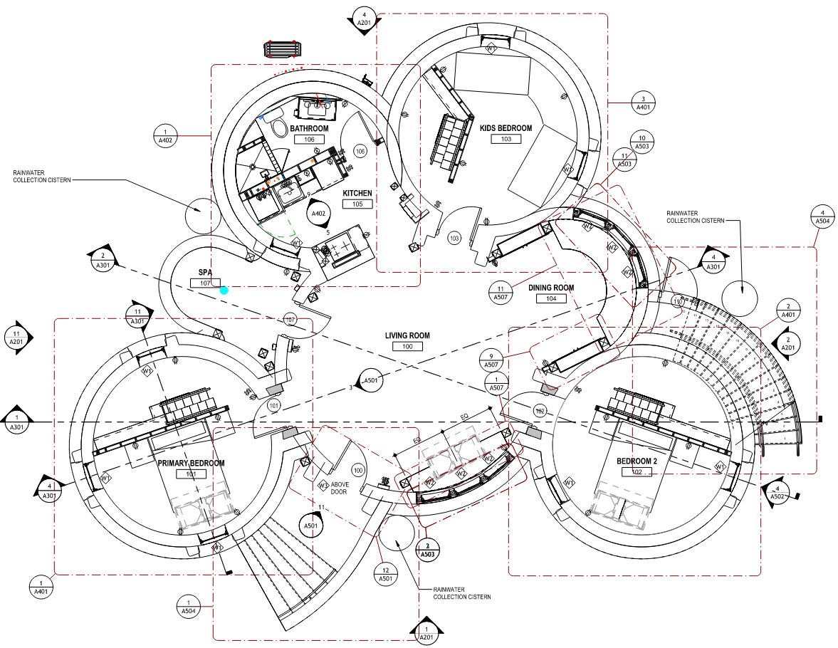
4-Dome Home Architectural Reference Floor Plan – Click to Enlarge
A lot of the initial prerequisites for starting an HVAC design will lie in the architectural floor plan where equipment will also be placed. The image below is the floor plan of the Earthbag 4-Dome Home from which these details were determined.
Equipment for the mechanical design to cover cooling/heating for the rooms and ventilation/exhaust for the bathroom/kitchen included 1-Ton Mini-Split Systems for each primary room, an exhaust fan for the bathroom, and a downdraft blower system for the kitchen area.
Cooling/Heating Loads for the primary rooms as stated previously are reliant on insulation of the building, total square footage, miscellaneous heat gain (windows, electronics, etc.), and location design parameters.
Specifying equipment for heating and cooling requires a bit of info but a number of common HVAC rules apply to this space. For example, a common widely used rule when designing airflow for spaces includes calculating airflow at a minimum of 1 = CFMSF. From here, we can work with a number of design conditions and project info to begin our design such as these items listed below.
PROJECT INFO
Here are the specifics these designs are based on:
Approx. Total Square Footage: 1,145 sq ft
Design Parameters
- Entering Air Temperature (Wet Bulb): 80 Degrees Fahrenheit
- Exit Air Temperature (Dry Bulb): 67 Degrees Fahrenheit
Exterior Building Insulation
- Exterior Walls: Earthbag Construction – Insulation Value: R-2 (updates coming for this)
The main item to take into consideration when gathering the cooling/heating load is identifying the sensible load (Qsensible) (BTU/Hr), or in other words, calculating the actual amount of energy transferred resulting in a direct temperature change. Once a sensible load is identified, another common rule of thumb is applying a percentage of margin for miscellaneous heat gain as stated previously such as windows, doors, insulation, and electronics. A 5% margin of error is typically applied however, with the utilization of earthbag constructed walls and poor insulation, a 10% margin will be applied for this design criteria.
SENSIBLE LOAD METHOD AND TABLE LOGIC
As stated in the previous section, the sensible load (Qsensible) for this building is defined as the amount of energy transferred resulting in a direct temperature change. This formula is typically used as the baseline load formula to identify how much energy (cooling) will need to be used in the building. The contents of this formula include our constant value of 1.08 which represents heat capacity of standard air near sea level, CFM (Cubic Feet per Minute) which represents a volumetric flow rate or the quantity of air being delivered per minute, and ΔT which represents the difference in the indoor design or desired temperature of the building and the return air temperature that will be supplied back to the unit design temperature. The formula for this calculation is defined as sensible load (Qsensible) equals 1.08 (sensible heat transfer constant) multiplied by the airflow volume (CFM) multiplied by the change in temperature (ΔT):
Now that a mathematical definition is defined for the sensible load (Qsensible), the variables in this same formula to accomplish this are defined as the airflow volume (CFM), Difference in Temperature (ΔT), and the sensible heat transfer constant of air which is 1.08. The CFM in this case includes values of a volume per time period(ft3minute)to identify an Airflow Volume:
ft3minute
= Airflow Volume
The difference in temperature consists of the Entering Air Temperature °F into the unit (return air) and the Exiting Air Temperature °F out of the unit into the targeted room (supply air). Mathematically, this is defined as Entering Air Temperature °F minus the Exiting Air Temperature °F equals ΔT or Difference in Temperature °F:
The sensible heat transfer constant is defined as 1.08:
For a room by room calculation using the formula of Qsensible = 1.08 × CFM × ΔT, initial square footage values gathered in the Revit program for each room are listed below in then “HVAC Load Values” table and shown after the Qsensible calculation. Here is a walkthrough for the living room Qsensible values that will also be established for the other spaces in the 4-Dome Home.
The initial approximate SF (square feet) of the living room is estimated as 346 ft2:
Now that a SF is established for the space using Revit, a CFM value can be established for the living room.
For determining the appropriate CFM values, it is important to start with a commonly used guideline in the HVAC field of
1 CFM for every SF determined in the building which can be written as 1 = CFMSF
:
Using this guideline, the square footage (SF) can be plugged into the 1 = CFMSF
formula, replacing SF with 325 ft2 in our case:
After plugging 325 ft2 into the formula for SF, this provides a value of 325
ft3minute
for the CFM:
ft3minute
Now that a CFM value is established for the room, the ΔT = Difference in Temperature °F can be established as well. While utilizing this value, it is important to note that this temperature value will be used for all room locations as the Entering Air Temperature °F and Exiting Air Temperature °F for the indoor unit will remain the same.
In the typical room setting of the 4-Dome Home, the air that will need to be conditioned in this space in a worst case scenario will stand at about
80°F. Since the unit will be pulling this air back into the system, this can be classified as Entering Air Temperature °F:
Now for the desired target temperature of a room setting in the 4-Dome Home, the conditioned air will be leaving the unit at about 67°F. This can be classified as the Exiting Air Temperature °F:
With both temperatures determined for the space, Difference in Temperature °F (or ΔT) can be determined using the previous values of Entering Air Temperature °F = 80°F and Exiting Air Temperature °F = 67°F:
13°F is determined as the suitable ΔT = Difference in Temperature °F for each room.
Now that the values for the sensible load (Qsensible) are established for the living room, the entire calculation can be completed as sensible load (Qsensible) equals 1.08 (sensible heat transfer constant) multiplied by the airflow volume (CFM) multiplied by the change in temperature (ΔT):
The total calculated sensible heat load for the living room totals as 4563 BTU/hr. However, an additional 10% margin of error or assumed miscellaneous heat gain is factored in with the utilization of earthbag constructed walls and poor insulation. To calculate this 10% margin of error, this can be written as our total load (Qtotal) equals sensible load (Qsensible) multiplied by the 10% safety factor (0.10) followed by the addition of the sensible load (Qsensible):
The total calculated sensible heat load for the living room totals as 4563 BTU/hr. However, an additional 10% margin of error or assumed miscellaneous heat gain is factored in with the utilization of earthbag constructed walls and poor insulation. To calculate this 10% margin of error, this can be written as our total load (Qtotal) = sensible load (Qsensible) multiplied by the 10% safety factor (0.10) followed by the addition of the sensible load (Qsensible):
Using the values from the living room sensible calculation, we can substitute these values for our total load (Qtotal) = our sensible load for the living room (4563 BTU/hr) multiplied by the 10% safety factor (0.10) followed by the addition of the living room sensible load (4563 BTU/hr) to provide a total load (5019 BTU/hr):
The final total of 5019 BTU/hr represents the living room’s sensible heat load after a 10% margin of error. The “HVAC Load Values” below illustrate values reflected for the living room as well as all the additional spaces in the 4-Dome Home.
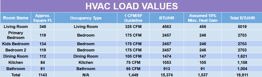
SENSIBLE LOAD METHOD AND TABLE LOGIC SUMMARY
This section outlines the basis and methodology used to determine the HVAC system selection and load requirements for the Earthbag 4-Dome Home. The design approach prioritizes simple, distributed equipment such as mini-split systems and localized exhaust to match room-by-room demands while reducing short cycling and maintaining reasonable installation costs. Key inputs including building size, insulation properties, and indoor/outdoor design conditions were used to establish airflow and temperature assumptions. The sensible load method served as the primary calculation approach, using standard HVAC relationships between airflow, temperature difference, and heat transfer to quantify room-level cooling requirements. A rule-of-thumb airflow rate of 1 CFM per square foot was applied to estimate air delivery, and a consistent temperature differential was used across all spaces to maintain uniform design conditions. Additional consideration was given to miscellaneous heat gains, with an increased margin applied due to the performance characteristics of earthbag construction. The resulting calculations provide a structured and repeatable framework for determining system capacity and support the selection of appropriately sized HVAC equipment for each space.
EQUIPMENT SELECTION & DISTRIBUTION
Before reviewing equipment selection for the 4-Dome Home, it is also important to establish and define the equivalents for these values to match with specification sheets for selections.
For equipment selection on this project, multiple indoor units will be used for cooling per main room in the building. 4 total indoor units will be used rated for a maximum of 14 MBH and 307 CFM which is supplied from one outdoor heat pump system. This outdoor heat pump system is rated as a 3-Ton Unit, however this operates at a desired temperature between the minimum and maximum amount of BTU/hr. Because this outdoor unit is rated for conditioning between 4,800 BTU/hr – 12,000 BTU/hr, this provides a steady buffer as operating at the minimum provides us with the amount of cooling needed as shown below:
Indoor Unit Rating = 4800 BTU/hr
Total Indoor Units = 4
Indoor Unit Rating × Total Indoor Units = 4800 BTU/hr × 4 = 19,200 BTU/hr
With 19,200 BTU/hr being the total amount of cooling available between 4 indoor units operating at the minimum, this meets the cooling demand shown in the “HVAC Load Values” table of 16,911 BTU/hr as well as operating at an energy efficient quota to prevent short cycling, unit wear & tear, as well as lower energy usage. However, if future conditioning is needed for the space, a future indoor unit can be provided given a 3-Ton unit in comparison to a 1.5-Ton that meets the minimum. This additional buffer also provides indirect conditioning to smaller spaces such as the bathroom, kitchen, and the dining room.
FUTURE CONDITIONING EXAMPLE:
The use of the possible future conditioning of the 4-Dome-Home given the earlier mentioned installation of the 3-Ton unit entails various items. Multiple scenarios outline the need for additional cooling, such as a future add-on to the space (renovations to the building increasing square footage), an updated occupancy expectation for day to day use in the building (residential style building possibly converted into small commercial spaces), or even additional heat gain from equipment that will be consistently used in the space (incandescent lighting or new appliances that reject additional heat)
The image below represents a Daikin Submittal Data Sheet illustrating and providing data on the outdoor heat pump unit as well as the indoor fancoil units that will be used. This data sheet represents the equipment that is selected to condition the Earthbag 4-Dome Home and acts as a reference for the previous calculations provided.
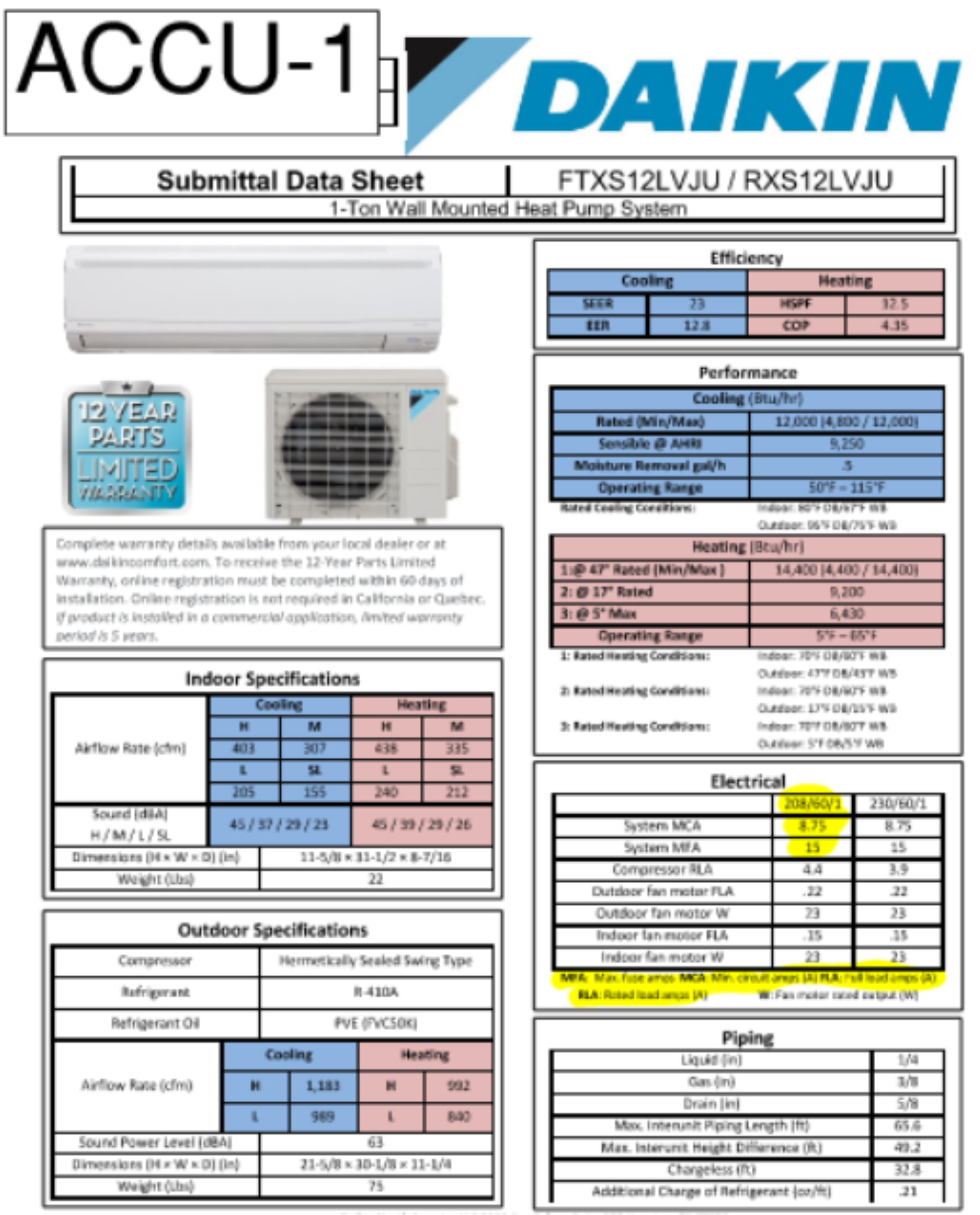
Heat Pump Mini Split System(Click to Enlarge)
For the exhausting purposes of this space, the bathroom and the kitchen will be exhausted via a ceiling exhaust fan and a range hood exhaust fan. Per the International Mechanical Code, bathrooms require an exhaust rate at a minimum of 50 CFM per water closet. For design purposes, the conditioning CFM for the bathroom is 65 CFM, 80 CFM is provided for the bathroom to exhaust a negative pressure while occupied. This same process is used while sizing an exhaust system for the kitchen. Because the kitchen is a space where heat and fumes will need to be exhausted, this design CFM will be at around 230 CFM to balance conditioning in this area as well as emptying fumes at a desired rate for the user.
Use multiple indoor units to distribute ~1.5 tons across the main rooms for even comfort.
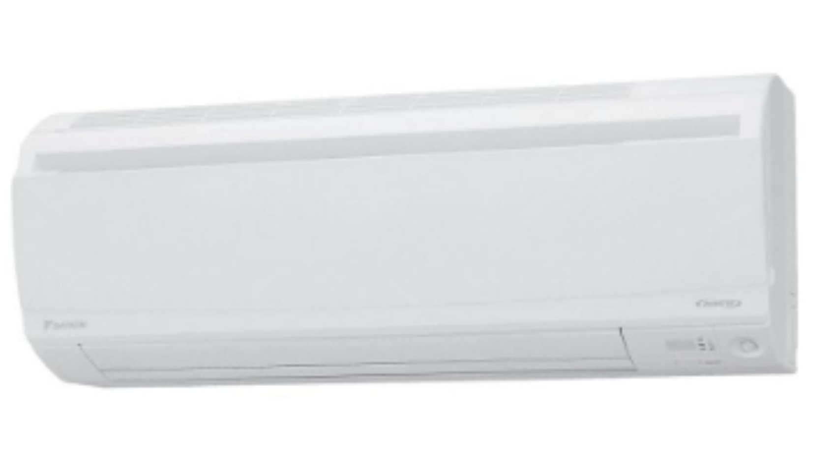
Indoor Unit (Click to Enlarge)
One outdoor heat pump (3-ton class with turn-down) provides headroom for diversity and future add-ons without short-cycling. With minimum capacity per head × number of heads > 17.7 MBH, you maintain an efficiency buffer while avoiding oversizing concerns.
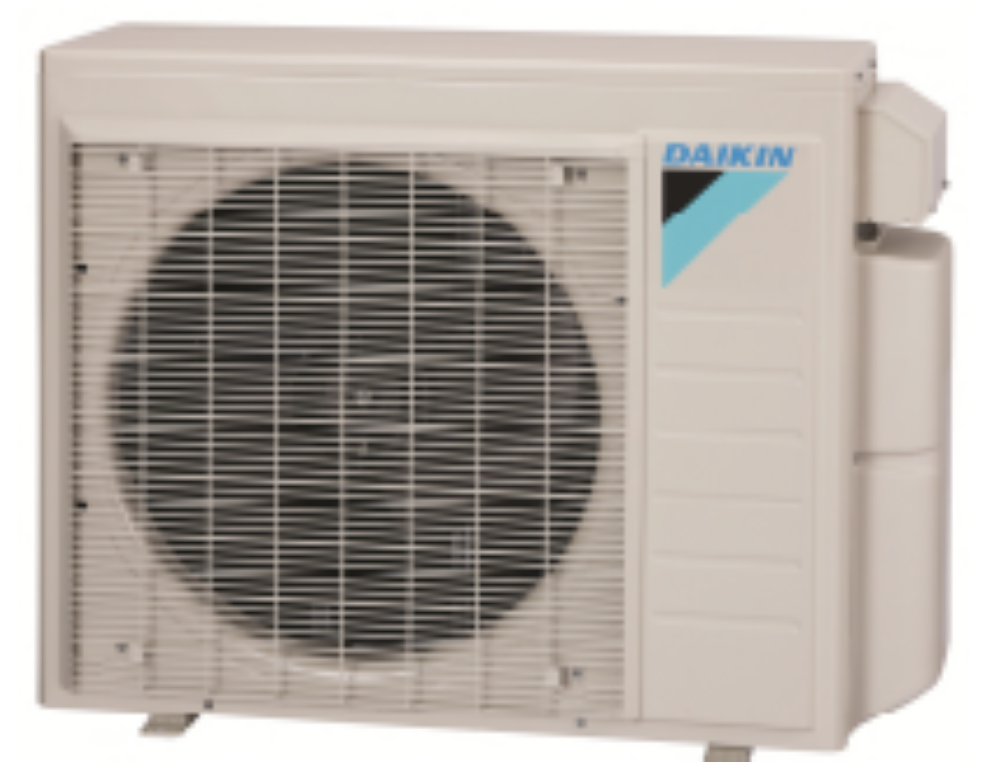
Outdoor Heat Pump (Click to Enlarge)
Exhaust: Bathroom ≥ 80 CFM (meets IMC ≥50 CFM/fixture; uses 80 CFM to ensure negative pressure). Kitchen ≈ 230 CFM via range hood/downdraft to control heat and fumes while coordinating with supply air to avoid depressurization.
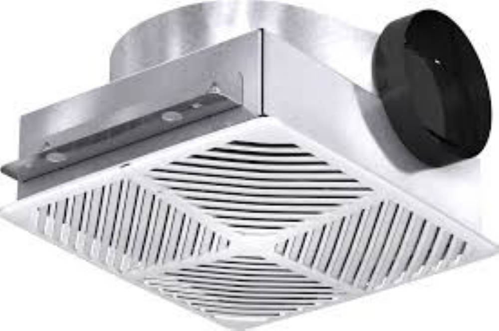
Bathroom Exhaust Fan (Click to Enlarge)
With the outdoor unit, indoor unit, and exhaust fans covered, these selections are also shown in the “Mechanical Equipment Schedules” image below. This graphic represents maximum capacities, design temperatures, and a basis of design manufacturer/ model number for reference along with calculations & methods shown in sections throughout the HVAC section.
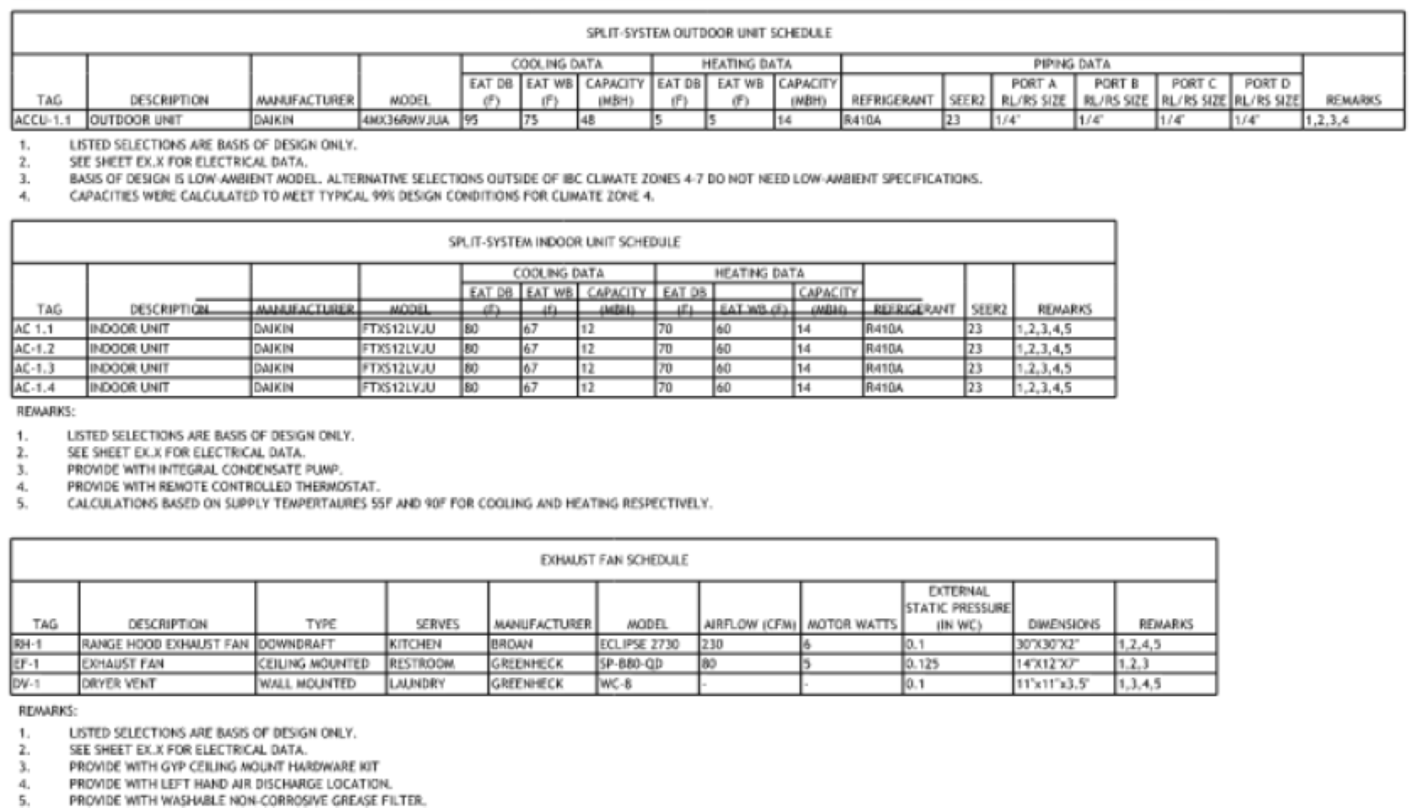
Mechanical Equipment Schedules (Click to Enlarge)
EQUIPMENT SELECTION & DISTRIBUTION SUMMARY
This section defines the equipment selection and distribution strategy for the Earthbag 4-Dome Home based on the previously calculated HVAC loads and design criteria. The system uses multiple indoor fan coil units connected to a single outdoor heat pump to distribute cooling across primary spaces while maintaining flexibility and efficiency. By operating the indoor units at their minimum capacity, the system meets the total cooling demand while reducing the risk of short cycling and limiting energy consumption. The selected 3-ton outdoor unit provides additional capacity for future expansion, increased occupancy, or added internal heat gains without requiring system replacement. Exhaust design for the bathroom and kitchen is based on code minimums and adjusted airflow rates to maintain proper ventilation and negative pressure where needed. Equipment selections are supported by manufacturer data and summarized in mechanical schedules, while the final system layout illustrates how all components integrate within the building. Overall, this approach provides a balanced system that aligns equipment capacity, airflow distribution, and future adaptability with the project’s design intent.
MECHANICAL PLAN IMAGES
The following figure below presents the final overall mechanical system layout for the 4-Dome Home, summarizing the heating, ventilation, and air distribution strategies described in this section. The image illustrates equipment locations, primary ductwork routes, ventilation paths, and system relationships to show how the mechanical components are integrated within the building configuration. This overview is intended to serve as a visual reference that supports the preceding design assumptions, calculations, and system selections, and provides context for coordination between mechanical elements and the architectural layout.
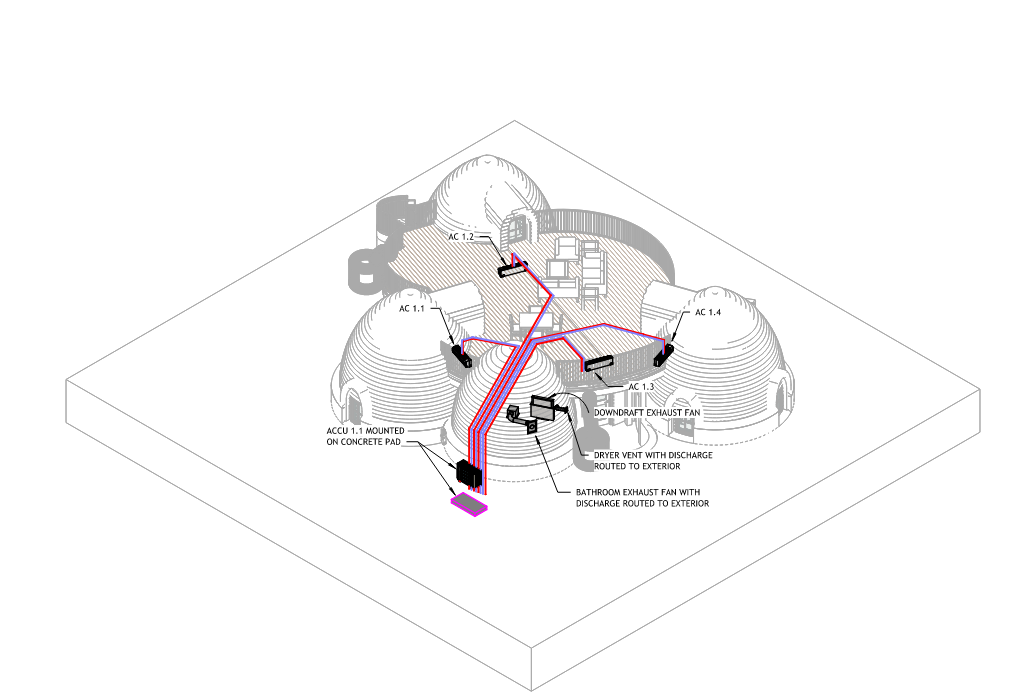
Mechanical Isometric View (Click to Enlarge)
MECHANICAL SUMMARY
This mechanical section presents a complete approach to HVAC system design for the Earthbag 4-Dome Home, integrating load calculations, equipment selection, and system distribution into a coordinated solution. The design is based on key building characteristics such as room sizes, insulation performance, and architectural layout, with an emphasis on sensible cooling and simple, distributed equipment. Cooling loads were determined using the sensible load method, applying standard HVAC relationships between airflow, temperature difference, and heat transfer, along with a rule-of-thumb airflow rate of 1 CFM per square foot and an increased margin to account for additional heat gains associated with earthbag construction. These calculations established the required capacity for each space and informed equipment sizing. The system utilizes multiple indoor mini-split units connected to a single outdoor heat pump to provide room-by-room conditioning while minimizing short cycling and maintaining energy efficiency. The selected equipment capacity meets current load demands while allowing flexibility for future expansion or increased internal gains. Ventilation and exhaust strategies were developed in accordance with code requirements, with adjusted airflow rates to maintain proper indoor air quality and pressure relationships. Mechanical schedules and system layout diagrams further define equipment performance, locations, and integration within the building. Overall, the design provides a balanced and adaptable HVAC solution that aligns calculated loads, equipment performance, and distribution strategy with the functional and environmental goals of the project.
ELECTRICAL
For the electrical design of the Earthbag 4-Dome Village, the goal was to provide a simple, code-compliant, and energy-efficient electrical distribution system that supports the daily operation of each dome while maintaining affordability and reliability. The electrical system serves as the “nervous system” of the structure—distributing power to lighting, receptacles, and equipment efficiently and safely throughout the space. The overall design follows NEC (National Electrical Code) guidelines, particularly in service sizing, conductor selection, overcurrent protection, grounding, and load diversity.<
The electrical service for the entire 4-Dome cluster was designed as a single 120/240V, 1-phase, 3-wire system, serving a main distribution panel rated at 200A.
Utilizing a 120/240V 1-phase, 3-wire system was chosen for the 4-Dome Home application mainly because of the accessibility, the cost, & the ease of installation. In common residential applications, one will most likely always find 120/240V service powering the building. This is because most residential applications only obtain small loads of equipment (outlets, lighting, ceiling fans, etc.). Larger equipment in homes such as water heating, HVAC units, and appliances commonly utilize the most electricity in a home, and most times there is only one of each of these items in a home. With a small quantity of the larger equipment in a home, a larger electrical service in terms of voltage is almost never needed as manufacturers produce this equipment in the 120/240V range specifically for this reason. This allows for the occupant or homeowner to operate equipment at a lower price and save month to month based on the kilowatts used per hour for each equipment.
Each dome’s internal circuits are derived from this central service, balancing loads across both phases to minimize neutral current and voltage imbalance. The electrical demand for this project is relatively low, reflecting the modest mechanical equipment loads, limited number of receptacles, and LED lighting usage.
Panel load calculations were performed in accordance with NEC Article 220 using both general lighting and small appliance demand factors. Each dome includes a combination of lighting, receptacle, and small fixed equipment loads. The connected and demand loads were determined using the following assumptions and equations.
In each circuit breaker in the panel for the 4-Dome-Home, that circuit will carry a certain amount of power based on what is connected to it. This can be classified as a Volts- Ampere:
VA = Volts- Ampere = Apparent Power
According to NEC Article 220, assumptions for an appropriate VA per SF and demand factors based on each the usage type can be referenced as shown in the “Electrical Load Demand Values” Table. The electrical demand factor is the ratio of a system’s maximum demand (peak load) to its total connected load, representing the fraction of the total potential load actually used at the peak moment, and is always less than or equal to one (or 100%). It helps engineers size electrical services by acknowledging that not all connected devices run simultaneously at full power, allowing for smaller conductors and equipment than a full-load calculation would suggest, thus saving costs. The first thing that has to be established is the square footage (SF) of the space:
SF = Square Footage
After the square footage is established, separately an approximated Demand Load (VA) can be established by multiplying the Demand Factor by the
Approx. Connected Load (VA):
Demand Load (VA) = Demand Factor × Approx. Connected Load (VA)
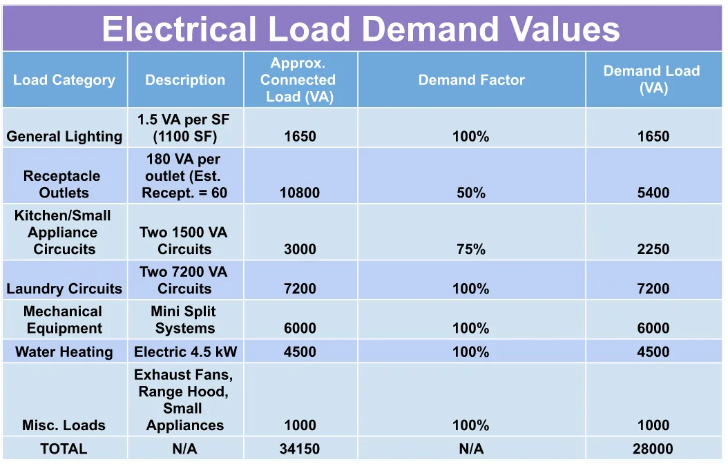
HVAC Load Values – Click for Source Table
From this demand load, the estimated calculated service current is approximately 117A at 240V before any rough panel calculations, making a 200A main panel a suitable and conservative selection to allow for future capacity. A 3/0 AWG Cu (American Wire Gauge Copper) feeder with a #6 AWG Cu equipment grounding conductor was sized based on NEC Table 310.16, assuming THHN (Thermoplastic, High Heat Resistance, High Heat Rating, Nylon Jacket) conductors in conduit with 75°C terminations.
Lighting fixtures throughout the domes are high-efficiency LED downlights and surface fixtures with an average design illuminance of 20–30 foot-candles per room, conforming to ASHRAE 90.1 energy efficiency recommendations. While the 4-Dome Home lighting will be LED based, incandescent lighting is also available for installation. With each room in the 4-Dome-Home designed to be circuited based on all loads in the room in contrast to a dedicated lighting circuit, the allowable watts per circuit (1,920 W) allows for the additional load of incandescent as the general circuit for each room captures only about 200W. With incandescent light bulbs ranging in about 40 -100 Watt range, this provides a large additional cushion for this installation. Lighting controls consist of wall switches located at entry points, with occupancy sensors installed in bathrooms to reduce unnecessary energy consumption. Receptacle distribution follows NEC 210.52 spacing requirements, ensuring no point along a wall is more than 6 feet from an outlet.
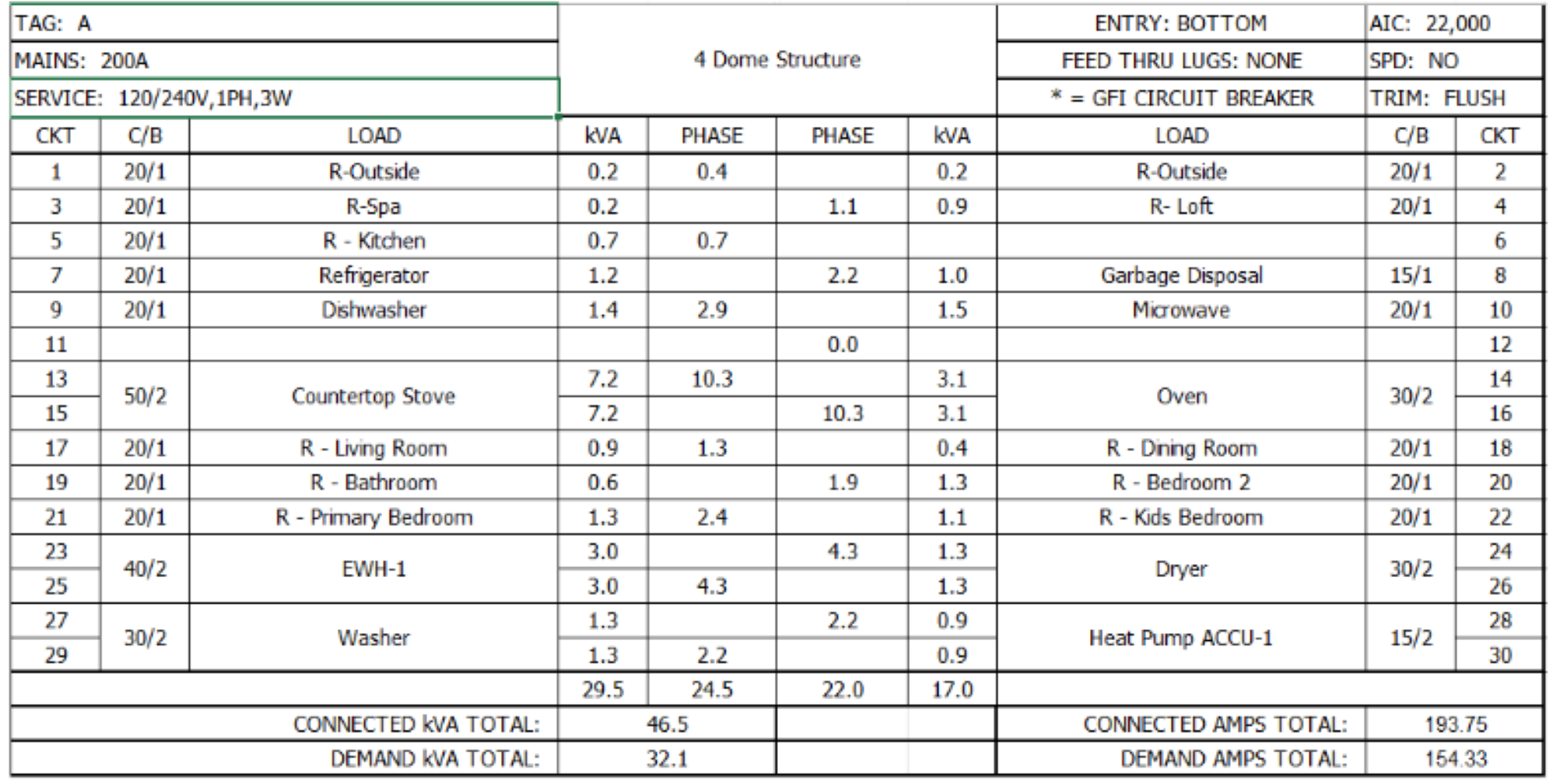
4-Dome Home 240/120 – 200 Amp Panel Schedule – Click to Enlarge
Based on the panel in the image above and comparing these to the initial table for assuming an electrical service, a 200 amp panel still remains suitable for this application. While derating (operation of equipment below its maximum capacity) receptacles at 50% percent and small appliances at 75% per NEC Article 220, our total load for the 4-Dome Earthbag structure comes in at 193.75 total amps and a derated load of 154.33 amps.
ELECTRICAL PLAN IMAGES
The following figure presents the final overall electrical power for the 4-Dome Home, summarizing the power distribution and equipment connections described in this section. The image illustrates panel locations, primary circuit routing and device coordination to demonstrate how electrical systems are integrated within the building configuration. This overview is intended to provide a visual reference that supports the preceding design assumptions, load calculations, and circuiting strategies, and to aid coordination between electrical components, and the architectural layout. Key items for navigation throughout this plan include:
- Circuit Naming/Numbering for each dedicated breaker in the panel; Example (A-26 for Panel A, Breaker number 26)
- Symbol Identification for Duplex Receptacle, GFI Receptacle, 240V Receptacle (Reference Electrical Plans)
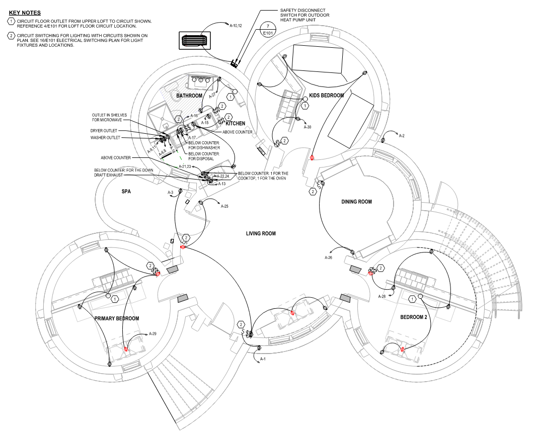
Electrical Power Plan – Click to Enlarge
The following figure presents the final overall lighting plan for the 4-Dome Home, summarizing the lighting placements and switching connections. The image illustrates lighting locations, primary circuit routing and switching coordination to demonstrate how lighting systems are integrated within the building configuration. This overview is intended to provide a visual reference that supports the preceding design assumptions, lighting selections, and the architectural layout. Key items for navigation throughout this plan include:
- Lighting Fixture Specification by Alphabetical Tag; Example (A, B, C, etc. next to fixture)
- Switching pattern/circuit denoted by the switch symbol ($)
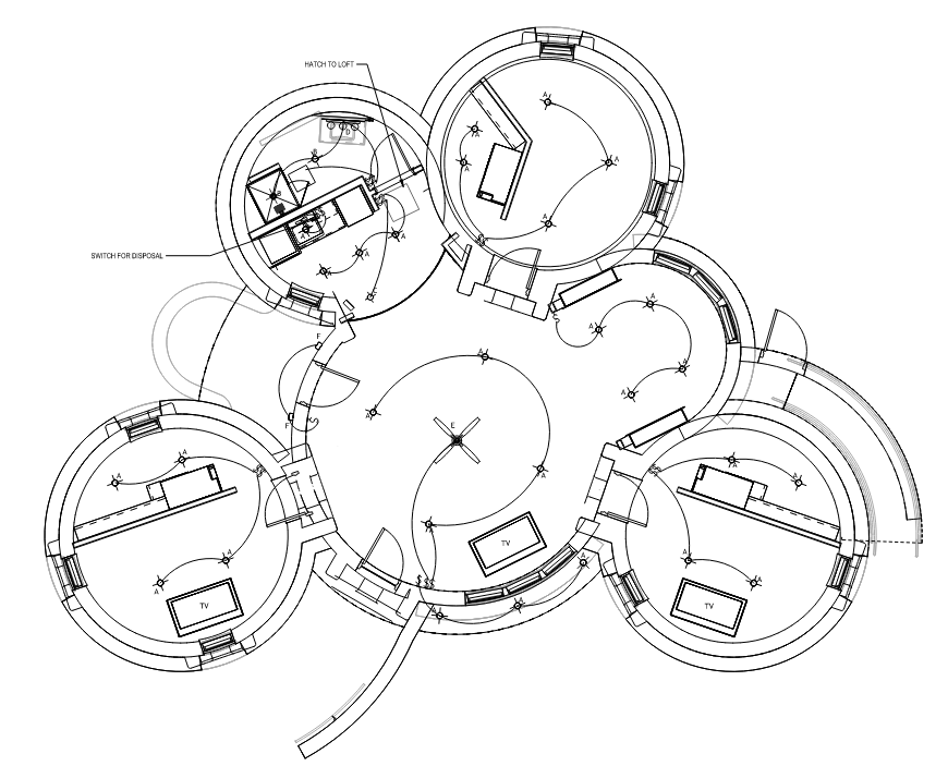
Electrical Lighting Plan – Click to Enlarge
ELECTRICAL SUMMARY
This electrical section outlines the design of a simple, code-compliant, and efficient power distribution system for the Earthbag 4-Dome Home. The system is based on a 120/240V, single-phase, 3-wire service feeding a 200A main panel, selected for its practicality, cost-effectiveness, and compatibility with typical residential equipment. Load calculations were performed in accordance with NEC Article 220, using square footage-based assumptions and demand factors to determine connected and diversified loads. These calculations resulted in a service demand that supports the selected panel size while maintaining additional capacity for future expansion. Conductors, overcurrent protection, and grounding were sized per NEC requirements to ensure safe and reliable operation. The design incorporates energy-efficient LED lighting, standard receptacle distribution per NEC spacing requirements, and basic control strategies such as wall switches and occupancy sensors to reduce energy usage. Circuiting is arranged by room to simplify distribution while allowing flexibility for additional loads such as incandescent lighting. The system also supports future integration of renewable energy systems through provisions for solar backfeed and battery storage. Overall, the electrical design provides a balanced approach that meets current load requirements while maintaining safety, efficiency, and adaptability for future needs.
EV Charger Selection & Design
*Design for EV charger hasn’t been incorporated into the 4-Dome Home plans, as well as the load for this equipment to the panel (This may require the panel to be upsized).*
PLUMBING
For the plumbing design of this space, the foundation of the layout begins with identifying all plumbing fixtures and determining their individual and combined water demands. These fixtures serve as the primary drivers for the design, influencing both the sizing of the water distribution system and the required capacity of the hot water supply. The design intent is to create a system that delivers reliable performance, maintains reasonable velocities to minimize noise and wear, and ensures pressure balance throughout the structure.
Similar to how the mechanical system conditions the air for comfort, the plumbing system serves as the “circulatory system” of the building—delivering clean water efficiently to every fixture and carrying away wastewater through properly sized piping. The overall approach focuses on using International Plumbing Code (IPC)standards to translate fixture counts into Water Supply Fixture Units (WSFU), convert these into GPM (gallons per minute), and then select appropriate pipe sizes that maintain practical flow velocities. Once total flow rates are known, water heating capacity is established by comparing fixture demands and usage patterns to the first-hour rating of a tank-type water heater.
This method ensures that the system is both functional and economical, offering consistent hot and cold water delivery even under peak demand conditions while aligning with the project’s broader goal of energy efficiency and low-cost sustainability.
WATER DISTRIBUTION METHOD
In plumbing system design, each fixture is assigned a Water Supply Fixture Unit (WSFU) value, which represents its relative demand on the potable water distribution system. These values are standardized in plumbing codes and engineering references, and they allow the designer to convert a list of fixtures into an equivalent demand load that can be used for pipe sizing, pressure calculations, and water heater selection. The table below summarizes the WSFU values for common residential and commercial fixtures, distinguishing between cold, hot, and total supply demand. These values are sourced from the International Plumbing Code (IPC) and are used in conjunction with probability curves and sizing charts to estimate peak flow rates throughout the system. By translating fixtures into WSFUs, the design process remains consistent, code-compliant, and scalable for different building types and occupancy conditions.
Per the International Plumbing Code, Chapter 6 Water Supply Distribution, GPM values per fixture can be found along with minimum connection sizes for each fixture. Using this method, this gives us a peak demand in a hypothetical scenario where all fixtures are being used at once as shown in the table below for total GPM values. Another method can be used using the Water Supply Fixture Units to then tally a total number for a GPM to give us a more accurate measure of this estimation. As shown in the table below and using the charts from IPC below, a value of 6.7 WSFU can be used to ultimately obtain a flow rate of about 18.4, which is accurate in comparison to our fixture based GPM value of 17.05. For a worst case scenario, the higher value will always be assumed, so determining a pipe size will be based on the higher GPM of 18.4.
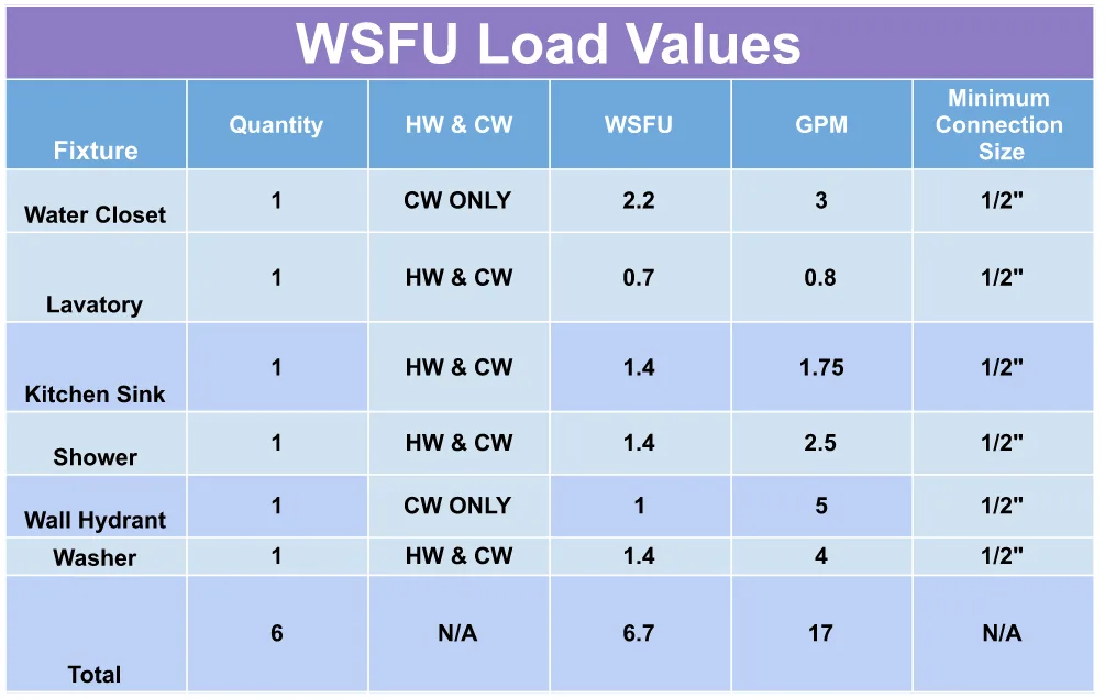
WSFU Load Values -Click for Source Table
Below is an image of fixture types classified by private or public occupancy. In this scenario, a “private” occupation will be used because the 4-Dome Home won’t be occupied as a public setting such as a grocery store, gym, etc., where multiple fixtures of a singular type will not be used simultaneously. Also listed in this chart are the types of “supply controls” such as flush tanks, flush valves, and even mixing valves. Water closets in this home will be flush tanks as these fixtures are less demanding in terms of gallons used. While also cross referencing the “WSFU Load Values” table above, a list of fixtures in the 4-Dome Home can be used to classify our total WSFU on the far right of the image below.
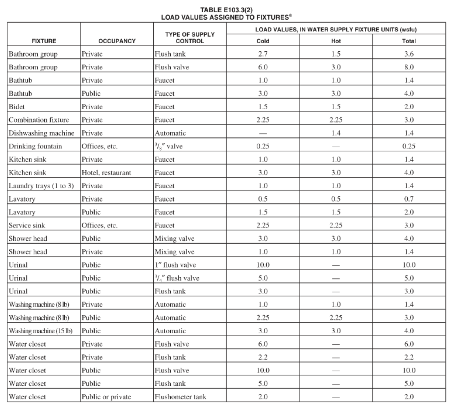
Fixture Load Values – Click to Enlarge
Now that a WSFU value of 6.7 is determined for all fixtures in the home, a GPM value can be determined using the table below to convert between the two quantities. In this table, there is a classification of systems for flush tanks and flush valves. As stated previously, the supply systems for predominantly flush tanks will be used because the fixture will be a flush tank water closet. Approximating the 6.7 WSFU to 7, the table indicates that for 7 WSFU values, this will be equivalent to 11.8 GPM.
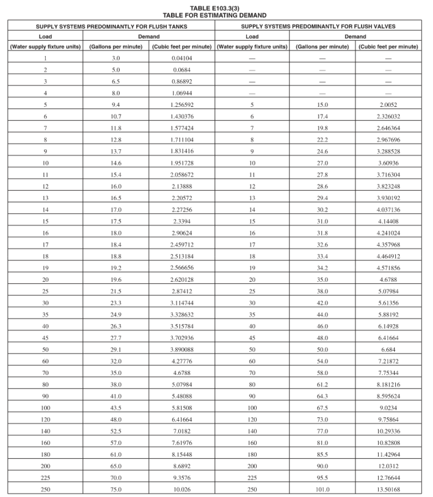
WSFU Load Values to GPM Units – Click to Enlarge
Now that a flow rate of 11.8 GPM for the building is determined, a conclusion for the pipe size can be drawn based on the flow rate and velocity, using the table below. For building applications with typical fixtures such as water closets, lavatories, sinks, etc., a velocity of 5 ft/sec is used to design to go along with our flow rate. Using the IPC Water Distribution table above, a minimum pipe size of 1-½” CW (Cold Water) is determined to be a reasonable entry for the Earthbag Dome. As CW & HW (Hot Water) piping are branched off from the main distribution line, the total WSFU value is decreased after a fixture connection is supplied, then providing an updated flow rate, determining our new main distribution line size.
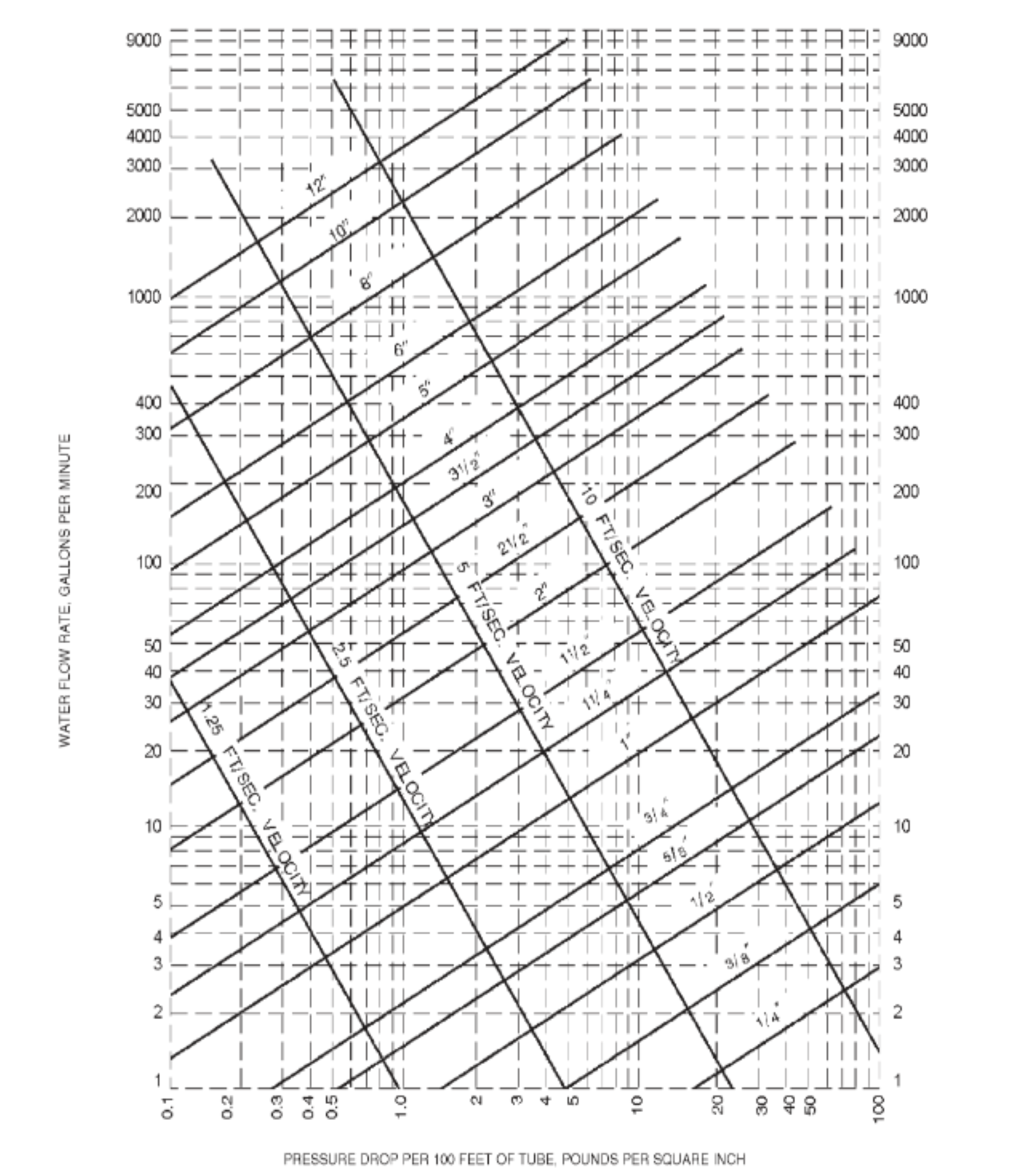
Domestic Cold Water Pipe Sizing – Click to Enlarge
WATER DISTRIBUTION METHOD SUMMARY
This section outlines the methodology used to determine water demand and pipe sizing based on Water Supply Fixture Units (WSFU). Each plumbing fixture is assigned a standardized WSFU value per the International Plumbing Code, allowing fixture loads to be converted into an equivalent system demand. These values are used alongside IPC charts and probability methods to estimate peak flow rates more accurately than assuming all fixtures operate simultaneously. For this design, a total demand of 6.7 WSFU was calculated and converted into a corresponding flow rate, with conservative assumptions made by selecting the higher estimated GPM value for sizing purposes. Fixture classifications were based on private occupancy conditions, with flush tank water closets selected to reduce demand. Using the calculated flow rate and a target velocity, the main water service was sized in accordance with IPC water distribution tables, resulting in a minimum pipe size that supports system performance and efficiency. As the system branches to individual fixtures, reduced WSFU values allow for progressively smaller pipe sizing while maintaining proper flow and pressure throughout the building.
HOT WATER HEATING
Now that a cold water service size has been established, water heating can now be determined for the building application. Hot water heating for this application is determined by a number of factors such as design temperatures, flow rates, and storage capacities. A number of these determinations can be used using ASHRAE’s guide on HVAC Applications from the Water Heating section such as assumed usage time, GPH (Gallons per Hour) values per fixture, and numerous formulas.
DESIGN TEMPERATURES
One of the first building blocks to start with includes the design temperatures. Cold water from our domestic service typically enters the building at about 40-50 degrees Fahrenheit and the desired end temperature is 110 degrees Fahrenheit. Calculating the temperature difference between the two provides a value of about a 60-70 degree temperature rise between the entering cold water and the desired end temperature.
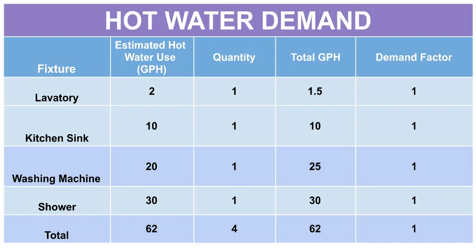
Hot Water Demand – Click for Source Table
Using the table above from ASHRAE’s guide, a table can be compiled based on GPH values per fixture along with demand factors for an “Apartment House” type of application. Using these numbers, a total GPH value of 62 is determined. Since an electric water heater will be utilized for this application, the storage capacity will have to be relied upon since this has a slower heating rate in comparison to an oil or gas water heater. This means that our first-hour rating will have to be similar or relatively close to our total GPH.
HOT WATER DEMAND
In addition to estimating total water demand using WSFU values, hot water system design requires an evaluation of fixture-specific hot water demand. The table below provides the recommended hot water draw rate in gallons per hour (GPH) for various types of fixtures, grouped by building occupancy type. These values represent peak hourly hot water usage at a delivered temperature of 140°F, and they are used to determine both the storage capacity and recovery rate required of a water heater or central hot water plant. By multiplying the number of fixtures by the listed GPH values and applying the appropriate demand and storage capacity factors, the designer can estimate the expected peak load and size the system accordingly. This method ensures that the hot water system is neither undersized—resulting in temperature drop and user discomfort—nor oversized, which increases equipment cost and standby losses.
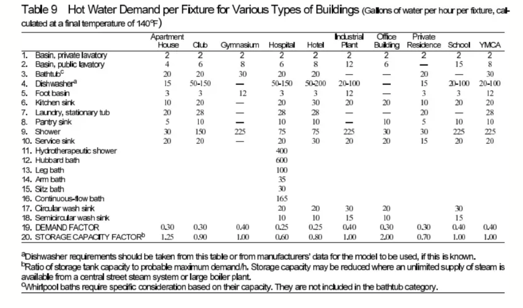
Hot Water Demand per Fixture -Click to Enlarge
A.O Smith provides a water heater (ENJB-40) with a 57 gallon first-hour rating including a 35 gallon capacity. This means that the water heater is able to store 35 gallons, however, the first-hour rating means that 57 gallons of water can be heated within the first hour of running out of hot water. Between the capacity of the tank and the first hour rating, this provides plenty of hot water for our fixtures in the Earthbag Dome.
The following figures below presents the final overall plumbing layout for the 4-Dome Home, summarizing the domestic water distribution, sanitary drainage, and venting strategies described throughout this section. The image consolidates primary piping routes and system relationships to illustrate how the individual plumbing components integrate within the overall building configuration and then connections before fixtures are included. This overview is intended to provide a visual reference that complements the preceding calculations and design assumptions and supports coordination between plumbing elements and the architectural layout.
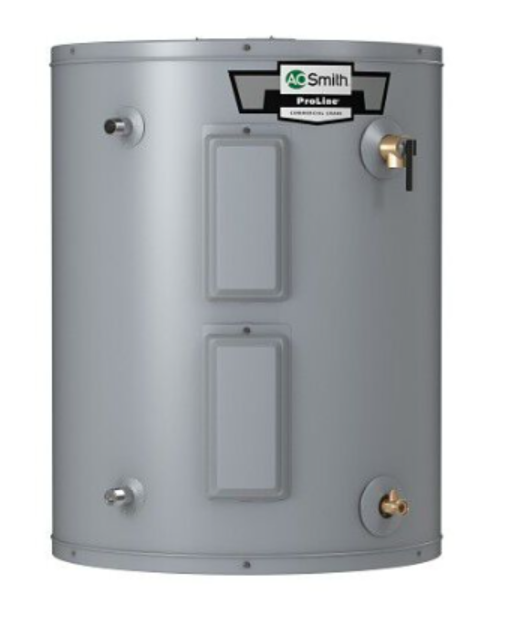
AO Smith ENJB-40 -Click to Enlarge
HOT WATER HEATING SUMMARY
This section defines the basis for sizing the hot water system by evaluating design temperatures, fixture demand, and storage requirements. The design begins by establishing a temperature rise between incoming cold water and the desired hot water supply, which is used to determine the heating requirement for the system. Fixture-specific demand values, expressed in gallons per hour, are then applied along with appropriate demand factors to estimate peak hot water usage for the building. Based on these calculations, the total hot water demand is used to guide equipment selection, with emphasis on matching the first-hour rating of the water heater to the expected load. Due to the use of an electric water heater, which has a slower recovery rate compared to other fuel types, the design prioritizes sufficient storage capacity to meet peak demand conditions and maintain consistent hot water availability.
PLUMBING PLAN IMAGES
The first image below represents the water supply distribution that will be installed in the 4-Dome-Home. Beginning with the “Water Meter By Utility Service”, the cold water entering the building shown in the diagram serves the plumbing fixtures listed as well as the water heater to supply hot water to required fixtures.
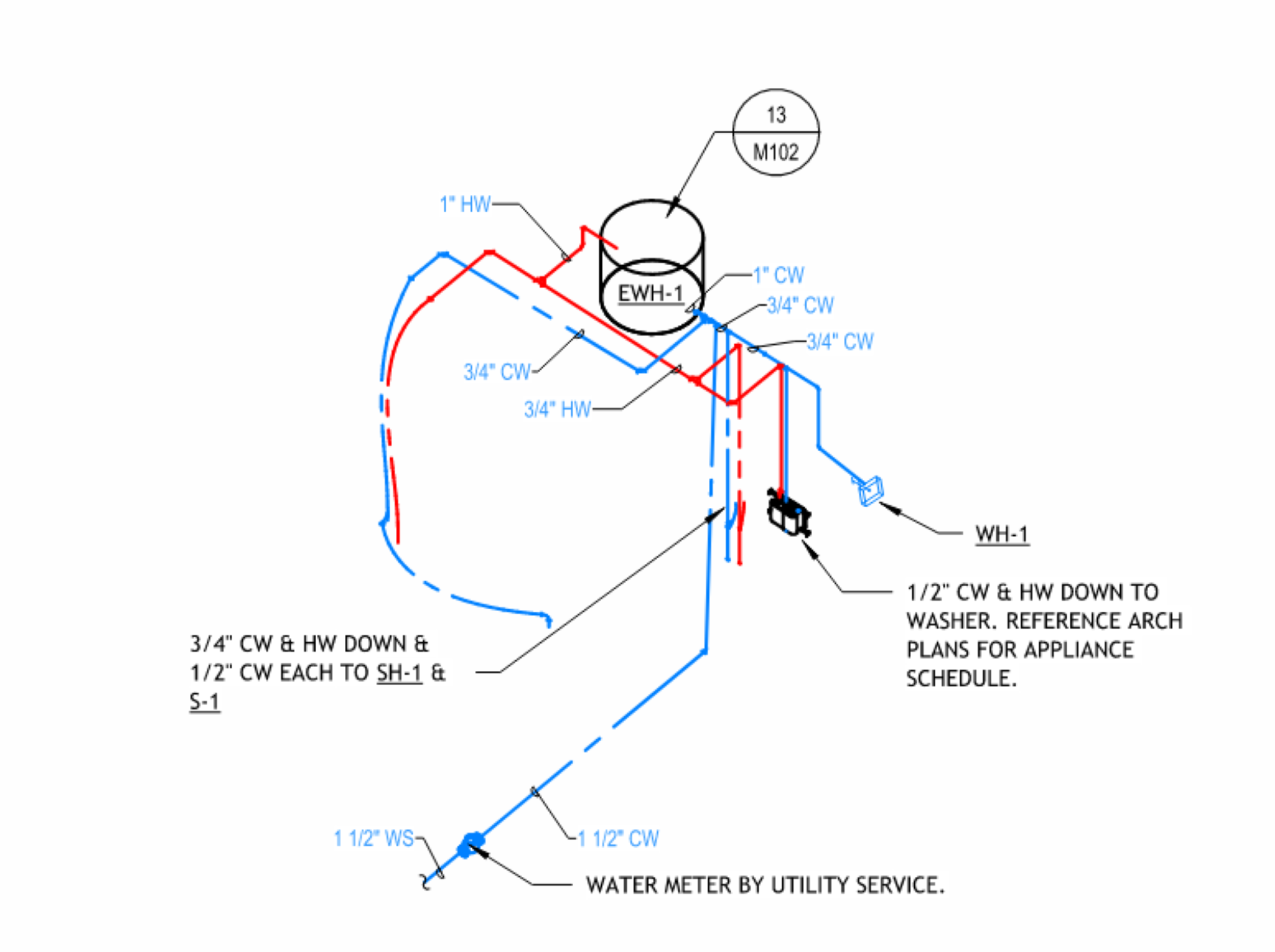
Caption: Water Distribution Isometric View -Click to Enlarge
The second image below represents the sanitary & vent piping representation from the fixtures to the sanitary exit/vent to roof. Beginning with the exit point showing on the image, all fixture connections indicated here will flow to this exit point. At the fixture connection, a vent stack will also be utilized for air admittance to ensure proper flow back to the exit point.
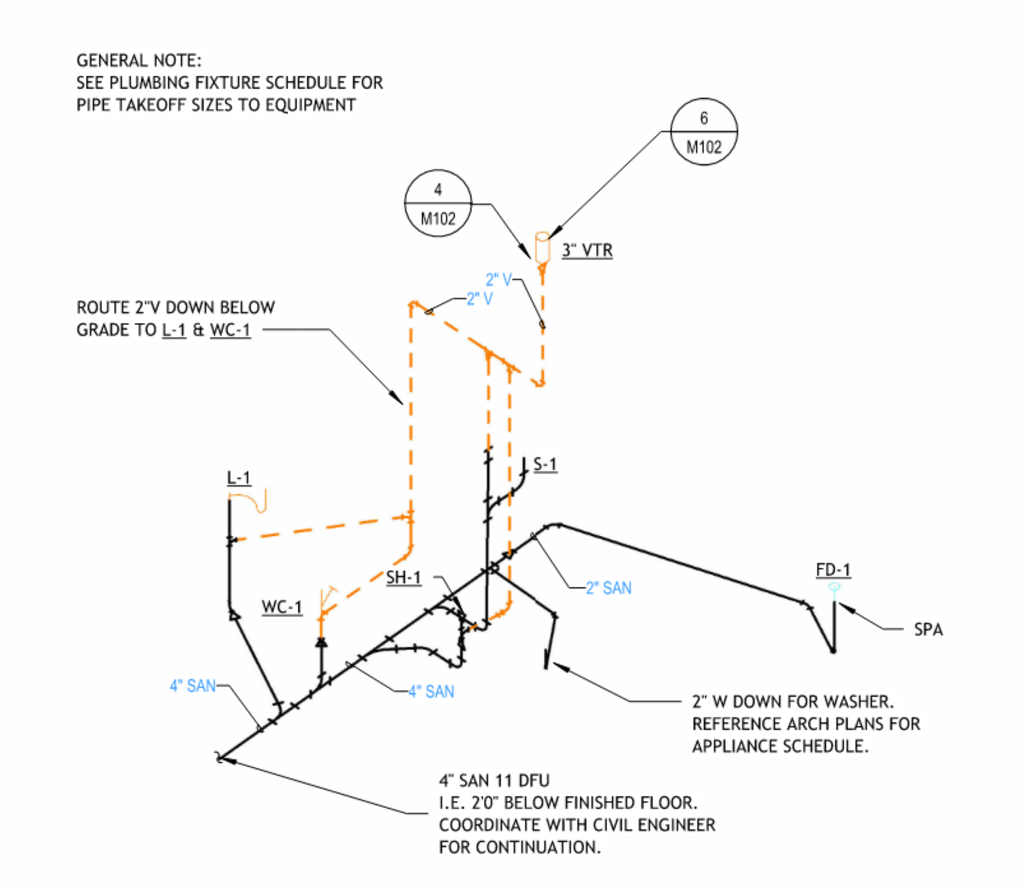
Caption: Water Distribution Isometric View -Click to Enlarge
PLUMBING SUMMARY
This plumbing section outlines the design of a code-compliant and efficient water distribution and drainage system for the Earthbag 4-Dome Home. The design begins with identifying all plumbing fixtures and translating their demands into Water Supply Fixture Units (WSFU), which are then converted into flow rates in gallons per minute to determine appropriate pipe sizing. Using IPC-based methods, the system is sized to handle peak demand conditions while maintaining practical flow velocities and balanced pressure throughout the building. A conservative approach is used by selecting the higher estimated flow rate to ensure reliability under worst-case usage. The domestic water distribution system is configured with a main cold water service that branches to individual fixtures and a water heater to supply hot water where required. Hot water system sizing is based on fixture demand, temperature rise, and first-hour rating, ensuring sufficient capacity for peak usage while maintaining efficiency. An electric storage water heater was selected to meet these requirements, balancing storage capacity and recovery rate. Sanitary drainage and venting systems are designed to properly convey wastewater and maintain system pressure through vent stacks, ensuring consistent and reliable operation. Overall, the plumbing design integrates water supply, heating, and drainage systems into a coordinated layout that supports performance, code compliance, and long-term functionality for the building.
OVERVIEW
The design of the Earthbag 4-Dome Village demonstrates that efficient, sustainable, and affordable building systems can coexist without compromising functionality or comfort. Each of the MEP systems—mechanical, plumbing, and electrical—was intentionally selected and sized to align with the broader goals of energy conservation, cost reduction, and long-term reliability.
From a mechanical standpoint, the use of distributed mini-split systems allows each dome to achieve localized comfort control with minimal energy consumption. By sizing these systems based on sensible load principles and incorporating high-efficiency heat pump technology, the design minimizes electrical usage while maintaining year-round thermal comfort. The choice of earthbag walls with an effective R-2 insulation value further supports this efficiency by reducing heat transfer and moderating indoor temperature swings.
The plumbing system complements these goals through a compact, code-compliant layout that reduces material usage and friction losses. Piping is sized to maintain balanced flow at moderate velocities, ensuring dependable water pressure and minimizing waste. The selected electric water heater provides a storage capacity and recovery rate that match the expected demand while keeping operational costs predictable and maintenance low.
Within the electrical system, deliberate load calculations under NEC Article 220 confirm a conservative yet efficient design. The integration of LED lighting, occupancy sensors, and balanced panel distribution enhances safety and energy performance. Additionally, the provision for future solar photovoltaic connection and energy storage demonstrates a forward-looking approach that supports renewable integration without costly redesign.
A separate MEP cost analysis spreadsheet has been developed to supplement this report and provide a clearer breakdown of anticipated material costs associated with the proposed mechanical, electrical, and plumbing systems. This spreadsheet itemizes fixtures, equipment, and system components by discipline and includes quantities, unit pricing assumptions, and total estimated costs to support transparency and future refinement. The cost analysis is intended to serve as a reference tool that can be updated as design decisions are refined, materials are substituted, or regional pricing conditions change.
MEP COST ANALYSIS SUMMARY
The cost analysis spreadsheet is organized by major building systems—mechanical, plumbing, and electrical—and evaluates each system based on material requirements, system complexity, and installation scope. From a cost perspective, primary drivers include the extent of distribution systems (ductwork, piping, and wiring), the number of fixtures and endpoints, equipment capacity requirements, and the level of system coordination required between trades. Mechanical costs are largely influenced by air distribution layouts, ventilation requirements, and system sizing, while plumbing costs are driven by fixture counts, pipe routing distances, and hot water generation needs. Electrical costs are impacted by overall load demands, lighting density, and the quantity of devices and circuiting required throughout the building.
Beyond initial construction cost, the spreadsheet reflects design decisions that balance efficiency, constructability, and long-term performance. System layouts appear to prioritize straightforward routing and standard installation practices, which can help reduce labor costs and simplify maintenance. The use of common system types and materials supports availability and ease of replacement, while centralized or well-organized distribution improves accessibility for future service. Additionally, the breakdown allows for evaluation of cost trade-offs between systems, helping identify where adjustments in design—such as reducing system complexity or optimizing layouts—can lead to overall project savings.
Together, these systems reflect an MEP framework that aligns with the principles of sustainability, affordability, and accessibility. The project’s open-source nature encourages replication by other designers seeking practical low-carbon solutions. By combining standard engineering practices with adaptable construction methods, the Earthbag 4-Dome Village stands as a scalable example of how resilient design can meet human needs while respecting environmental and economic boundaries.
SUMMARY
The 4-Dome Home Mechanical, Electrical, and Plumbing (MEP) Engineering page presents the complete open-source engineering design for integrating HVAC, electrical, plumbing, and energy systems into One Community’s Earthbag 4-Dome Home. It provides detailed calculations, engineering drawings, equipment specifications, installation guidance, and code-based design methods to help create a safe, energy-efficient, durable, and sustainable home. The page explains how the mechanical, electrical, and plumbing systems work together to maximize occupant comfort while minimizing energy and water consumption. It also includes downloadable resources, diagrams, and open-source documentation so others can replicate, improve, or adapt the design for similar sustainable construction projects. The overall goal is to make high-quality MEP engineering freely available, supporting affordable, resilient, and environmentally responsible housing worldwide.
FREQUENTLY ANSWERED QUESTIONS
Q: Where do I learn more about One Community’s earthbag structures?
The best place to start is on the Earthbag Village open source hub.
Q: I trust you’ve done your research correctly, can I just build one of your structures using this?
No. We won’t consider this research sufficient to build even our own structures until we’ve received a stamp on the final plans from an engineer licensed in the state we’ll be building in and finished construction of our first one. We’ll share those stamped plans here when we have them. We will also share anything new we learn through that process.