 One Community
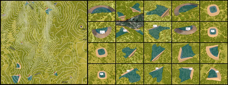
Open Source DIY Earth Dam Design & Construction for Water Retention, Pond & Lake Creation, etc.
This page is about earth dam construction for water retention purposes. Building a small to medium-scale earth dam like the ones described on this page can provide water for irrigation, aquaclture, recreation, ecosystem restoration, and other uses.
Note: We are not experts in earth dam design. We’ve just done an immense amount of research on the topic after identifying a need for earth dams as part of the open source One Community Highest Good Housing and Food components.
We share all we’ve learned with the following sections:
- What is Earth Dam Construction
- Why Open Source Earth Dam Construction
- Ways to Contribute to this Open Source Component
- DIY Earth Dam Construction Steps
- DIY Earth Dam Disaster Risk Mitigation
- Dam Risk Analysis, Assessment and Management
- Risk Communication and Emergency Preparidness
- Resources
- Summary
- Frequently asked questions
RELATED PAGES (Click icons for complete pages)


")


![]()
![]()


")
")
")
CLICK THESE ICONS TO JOIN US THROUGH SOCIAL MEDIA
![]()
![]()
![]()
![]()
![]()
![]()
![]()
![]()
![]()
![]()
WAYS TO CONTRIBUTE TO EVOLVING THIS SUSTAINABILITY COMPONENT WITH US
SUGGESTIONS | CONSULTING | MEMBERSHIP | OTHER OPTIONS
KEY CONSULTANTS TO THIS COMPONENT
Julia Meaney: Web and Content Reviewer and Editor
Loza Ayehutsega: Civil Engineer/Assistant Civil Engineer
Yi-Ju Lien: Environmental Engineer
WHAT IS EARTH DAM CONSTRUCTION
 Earth dam construction is a viable option in many places for water storage and pond or lake creation. Systems will vary from place to place, so the design of your water storage feature warrants flexibility and careful observation of the surrounding landscape. The ideal solution is one that maximizes water storage and minimizes human intervention. This can be accomplished by mindfully educating ourselves on the natural elements we are working with.
The earth dam construction content here is from hours of research on this topic. Our goal is to organize what we’ve learned into some broad guidelines and hopefully turn a nebulous and daunting task into a viable water-retention solution. The overall steps of the process are outlined in the flowchart below.

Earth Dam Construction Steps Flowchart – Click to enlarge
WHY OPEN SOURCE DAM CONSTRUCTION
Dams encircle the lower perimeter of where water wants to flow to create ponds that are replenished by both surface runoff and subsurface flow. Although water tanks are preferred for drinking water, they can cost 100x more for the same amount of water stored in an earth dam. The ponds and lakes created by small earth dams also develop valuable wetland ecosystems, beautiful recreation areas, aquaculture options, and large-scale water storage for emergency and/or agricultural use. Small DIY earth dams minimize flooding during the wet season, keep water from drying up during the dry season, combat erosion, and allow the standing water behind the earth dam to better percolate into the ground, recharging the groundwater and raising the water table. In addition, small DIY earth dams also lend the possibility of serving as small scale electricity generation for supplemental power needs through properly planned mini and micro-scale hydro power options.

Tamera Eco-Settlement Water Conservation Results: This Took Less Than 4 years
EARTH DAM CONSTRUCTION DETAILS
Our goal with this page is to share everything our research has taught us about DIY earth dam construction. There are many different types of earth dams that you can construct, but the basics of construction are the same. The image below shows the most common earth dams and we use the following sections to discuss each of these (and others) and the ways to build them:
- DIY Earth Dam Legal Considerations
- DIY Earth Dam Safety Considerations
- Sealing a Pond or Lake
- Types Of Earth Dams
- Earth Dam Construction Details
- DIY Earth Dam Construction Case Studies
- DIY Earth Dam Cost Analysis
- DIY Earth Dam Disaster Risk Mitigation
- Resources
- Summary
- FAQ
DIY EARTH DAM LEGAL CONSIDERATIONS
You must be aware of and adhere to local laws before constructing an earth dam. Failure to do this can lead to forced removal of your construction. Plan ahead for this because meeting with the local watermaster, local county authority for land use permitting, fish and wildlife services, and/or the state for permission can take 6 months or more
DIY EARTH DAM SAFETY CONSIDERATIONS
Depending on the size and location of your earth dam, you may also need to enroll a civil and/or structural engineer in the design process. Here are a few of the things to think about:
- Consider your materials for construction. Do you need an engineer to identify if they are sufficient for your purposes?
- Consider what would happen if your earth dam were to suddenly burst and release all its stored water at once. What is downstream from that? Do you need an engineer to make sure this will not happen?
- Consider the permeability and slope of your land. Could the water you are storing cause a landslide? Do you need an engineer to make sure this will not happen?
- Consider animal/ecosystem impacts from your pond and on your pond
- Consider your seismic zone
These and any other safety concerns need to be thought of and addressed from the beginning.

Constructing an earth dam without proper safety measures can result in structural failures, landslides, or ecological damage. Engaging engineers and addressing site-specific risks ensures the dam’s stability and the safety of surrounding areas, preventing catastrophic failures.
It’s a scary business, it’s scary designing, especially when a lot of dirt’s been moved and sheets of water are spreading across the landscape. That’s scary. And if it scares you too much, get someone in to do it.
~ Bill Mollison ~
SEALING A POND OR LAKE
Typically, 1.6 to 3 feet (0.5 to 1.0 meter) of clay is needed to seal an earth dam. The pond water level naturally fluctuates, resulting in periodic wetting and drying of the pond bed. When the bed is exposed and not submerged under water, the clay layer can crack as it dries and these cracks can go down about 1.6 feet (0.5 meters), so 3 feet (1 meter) is ideal to account for this natural cyclical process.
When enough clay is not available at the site of the pond, we must consider other alternatives to seal the pond bed. The benefits of having a pond for water storage outweighs the use of non-natural materials that may be needed. If a pond is leaking, these methods can be tried – ideally in this order if the goal is minimum effort:
COMPACTING OPTION
- Gleying – sealing with organic material, either with a layer of mashed, green, wet plant material or by allowing cows, ducks, and other farm animals to graze within the pond bed. The bed becomes compacted by their hoof action and as the manure decomposes, it forms a material that naturally seals small cracks. The basic process entails having a layer about 6-9 inches deep of green organic material (either plant or manure) over the pond bed (base and sides) and then covering this layer with soil, cardboard, plastic, etc.. The trapped material begins to decompose anaerobically. In cold areas, allow 1 to 2 weeks. In tropical areas, allow 1 to 2 days. Once the process is complete, remove the layer used to cover the organic material.
BLANKETING OPTIONS
- Imported clay – this is an expensive option. The imported clay can be spread and rolled 9 to 12 inches thick over the entire pond or the area with the potential leak.
- Bentonite ” bentonite* is a clay-powder from volcanic ash that swells when watered and it is this swelling action that seals a pond. When applying bentonite, start with a nice bowl shaped pond with 30 percent slopes and ensure that the surface of the pond bed is rock-free. Then, spread bentonite out thickly and place 1 foot of rock-free soil on top of the bentonite and roll it in. There are two types of Bentonite: 1) Sodium which has high swelling capacity and 2) Calcium with a negligible swelling capacity.
- Impregnated geofabric – When using bentonite impregnated geofabric, start with a nice bowl shaped pond having 30 percent slopes and trench all the way around the outside. Lay out the fabric and put bentonite on the overlapping sections and gravel in the trench to hold the fabric in place. Place 1 foot of rock-free soil on top of the fabric and roll it in. Once the water hits the fabric, it swells up and forms a seal. These come out like a natural swimming pool, they don’t muddy up at all.

TYPES OF EARTH DAMS
There are many different types of earth dams you can construct. This table shows the most common types.

Types of Dams – Click to enlarge
Here are all the good locations we could find for each of the above using a topo map, Google Earth, and 1-square-mile parcel of land.

Note: The Photoshop topo overlay in this image is not as accurate as the Sketchup overlays above and below.
We explore each of these (and a few others) with additional notes and more specific imagery below.
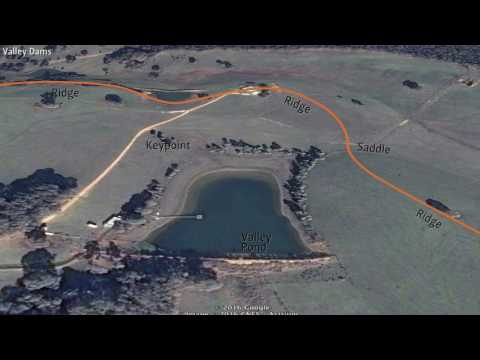
VALLEY DAM
")
Valley Dam Placement – Click to enlarge in a new window (2 MB)
Valley earth dams are constructed across a valley or gully. These dams, sometimes called a “barrier dam,” are most frequently used as energy systems. Especially when built in the path of a flowing or intermittent stream bed. These dams are also valuable for storing large volumes of water, as well as for irrigation. For these dams, it is particularly important to overdesign the spillway and accommodate any fish passage that has been obstructed due to dam installation.
RIDGEPOINT DAMS
")
Ridgepoint Dam Placement – Click to enlarge in a new window (1 MB)
Ridgepoint earth dams are located on flattened portions of descending ridges and are quite rare. It is composed of a single, horseshoe-shaped wall. These dams are most useful for water storage and runoff collection.

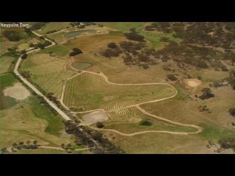
KEYPOINT DAMS
")
Keypoint Dam Placement – Click to enlarge in a new window (2 MB)
Keypoint earth dams are located in lower countries where hills transition from convex to concave. These dams are primarily used to store irrigation water and are amenable to being placed in series on descending contours. These are most appropriate for 4-12% slopes.
CONTOUR DAMS
")
Contour Dam Placement – Click to enlarge in a new window (2 MB)
Contour earth dams are located along hillsides where the contour widens on relatively flat terrain (slope of 8 percent or less). They are 3-sided and the front of the dam is either concave or convex to follow the contour. They are most useful for domestic livestock and aquaculture. These tend to be relatively expensive in comparison to their water storage capacity. Like keypoint dams, contour dams are amenable to being placed in series on descending contours. There is insufficient natural catchment so diversion channels or swales are essential.

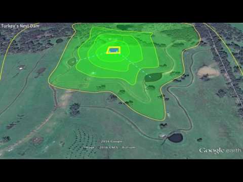
TURKEY NEST DAM
")
Turkey Nest Dam Placement – Click to enlarge in a new window (2 MB)
Turkey nest earth dams are earthen water storage tanks best placed on the highest available site with flat ground. These dams do not capture runoff, so they must be filled with external water sources. These are much cheaper than constructed tanks, but limited to use for irrigation, whereas constructed tanks can be used for drinking water as well. These dams should be at least 100 feet x 100 feet x 10 feet (providing approximately 0.6 million gallons of storage) to be cost effective.
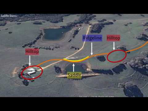
SADDLE DAMS
Saddle earth dams are unusual because this type of land feature is rare – a saddle between two hills. These dams have two walls. These dams are most useful for fire control and ecosystem/wildlife support. This type of dam typically ends up being the highest dam on the landscape and has the potential to fill from hill runoff.
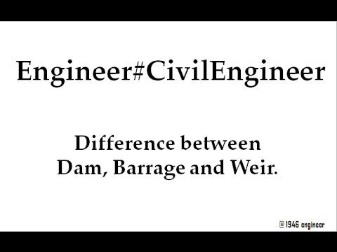
BARRAGE DAMS
A barrage earth dam is one of the least likely DIY dams you’d probably consider constructing. This is because they incorporate a large mechanical component to control gates that regulate the amount of water they store. Barrage dams are normally built near the mouth of the river and used to divert water for irrigation needs or limit the amount of water going down-stream. Water builds up behind these dams and a number of large gates are opened or closed to control the amount of water passing through. This allows the structure to regulate down-stream water while also stabilizing river water elevation upstream for use in irrigation and other systems.
Here’s a video about these commonly commercial-scale dams. It provides a good explanation of the difference in function between a traditional dam and a barrage dam.
DIY EARTH DAM CONSTRUCTION STEPS
 Here we discuss the steps for constructing your own earth dam. Again, we’re not experts in earth dam design or construction. We’ve just done an immense amount of research on the topic after identifying a need for earth dams as part of the open source One Community Highest Good Housing and Food components. We share here all we’ve learned with the following sections:
- DIY Earth Dam Planning
- Earth Dam Selection
- DIY Earth Dam Initial Assessment/Site Selection
- Taking Test Slices
- Water Storage Feature Design
- DIY Earth Dam Construction
DIY EARTH DAM PLANNING
Throughout the life of the project, engage in a dynamic thinking process and be flexible and receptive, allowing nature to be your guide. During the planning stage it is important to clearly define the purpose and overall desired outcomes of the project and identify the resources available. Include in your resource evaluation your financial resources, your equipment resources, the lay of the land, and personal and local knowledge base.
- Engage in a dynamic thinking process
- Set your goal to make the land resilient and vital
- Allow your design to change based on findings during construction
- Nature is the ultimate guide, make experiments, use applied knowledge
- Define project goals
- Budget
- Water volume
- Water uses. Ex: drinking, fire suppression, irrigation, etc.
- Identify resources
- Potential supplies
- Favorable slopes
- Elevations
- Key points
- Local construction methods
- Evaluate possibilities using a contour map
- Aridity of the area – Data available from the Global Aridity and PET Database
- Legal ramifications: Meeting with the local watermaster, local county authority for land use permitting, fish and wildlife services, and/or the state for permission can take 6 months or more.
Earth dam construction involves significant risks, including structural failure, environmental damage, and legal issues. Engaging engineers and complying with local regulations is essential to mitigate these risks, ensuring the project’s safety and sustainability while protecting downstream communities.EARTH DAM SELECTION
When working with nature, it is imperative to have a variety of applications that serve the same or similar end uses. With a water retention landscape, it is wise to have a mixture of earth dam types to meet your end-use needs. This is safer and usually easier. It also better prepares you for unpredictable natural events, such as seasonal and intraseasonal extreme weather variations. To select the appropriate number and types of earth dams, the following table can be utilized:

Dam Types, Uses, and Examples – Click to enlarge
Here are some additional guidelines:
- Observe the existing patterns of water movement
- Assess climate and topography to determine water potential
- Seek to work with and amplify the site’s natural characteristics
- Assess prevailing winds – they increase losses due to evaporation
- Aim to have multiple earth dam types to serve a variety of end uses
- High potential-energy dams: located high up, such as keypoint and ridgepoint dams
- High water volume dams: located on gentle slopes, such as valley dams
- Maximum value for money and effort spent is achieved when the resulting length of water retained behind the earth dam is 3x the length of the dam wall
DIY EARTH DAM INITIAL ASSESSMENTS/SITE SELECTION
It is crucial to have soil with sufficient clay content for the earth dam structure, as well as the pond bottom. Soil with at least 40 percent clay is necessary to build a water-tight earth dam, and to retain water in the pond. Given the importance of this criteria, it is worth the money to rent an excavator to dig and evaluate the soil at the potential earth dam sites identified in the step above. The “Taking Test Slices” section below discusses how to do this.
Use models and small experiments to more deeply understand the local landscape’s potential for water storage. It is very hard to work with free-draining soil (deep or coarse sands), rocky areas, and/or areas too steep or unstable. The bottom of gentle slopes are usually better choices.
If clay has to be brought in (versus mined on your own property), rethink the pond location and/or water storage method.
TAKING TEST SLICES
Taking test slices helps you understand the types of soil you will be dealing with. Using an excavator (if available), assess the geology 6 to 12 feet below the ground surface at around 6 different locations. You can go as deep as 15 feet, but beyond that returns diminish. Dig until an impermeable layer is reached near the depth you want your pond to be. This article called “soil permeability” explains well what you are looking for and why.
The geology can be significantly different just 30 feet away. In some areas it is helpful to have the excavator put each scoop in sequence so each layer can be assessed for clay content. The excavated materials (called the “overburden”) may need to be sorted to arrive at the correct clay content. Forty percent clay or more is the goal. If you don’t have 40 percent or more clay, another area on the property may need to be mined. The video below shows how to test and measure your clay content.
Note: For earth dam construction, it is preferable to use test slices over coring. This is because coring typically only provides an assessment for the first 3 feet below the ground surface and you are seeking to assess your soil between the depths of 6 and 15 feet.
Testing Soil for Clay Content
WATER STORAGE FEATURE DESIGN
Earth dams may not be the ideal solution for all locations and there are many different kinds of earth dams (see “Types Of Dams” above). Here are the key guidelines our research identified:
- Seek to minimize earth dam size
- Seek to maximize water retention
- Look at the resources you have
- If you have a valley, pick the narrowest point
- Minimize earthwork and disturbances/maximize undisturbed areas
- Use models and small experiments to test your ideas before starting construction
- Keep your thinking process dynamic/be open to change
- If you have to bring in clay, then rethink your pond location and/or water storage methods
- It is ok for your earth dam and water reservoir to leak, because subsurface and surface runoff are filling the pond
- If using your pond for fire suppression or irrigation, place the pond 100-250 feet above your area to irrigate/protect so it can function without electricity. For fire suppression, talk with the fire department to outline the exact place, including access and fittings.
Sepp Holzer uses a water-retention-landscape style where the surrounding forest is your water reservoir. Water from your dammed area spreads through the surrounding ground and helps develop a lush landscape. The picture and video below are about one of Sepp’s earth dams and the landscape like this that he created.
Tamera Eco-Settlement Water Conservation Results: This Took Less Than 4 years
WATER IS LIFE - The Water Retention Landscape of Tamera
DIY EARTH DAM CONSTRUCTION
A successful water retention landscape can be created using basic principles and well-established parameters. At a minimum, a water retention landscape consists of earth dams, embankment ponds, spillways, and erosion control interventions. On some landscapes, sediment traps, diversion drains, and swales make sense. In simple terms, assure that the local soil has at least 40 percent clay, all earth dam walls can be less than 20 feet (6 meters) high and still meet minimum volume/end-use requirements, and that the pond length behind the earth dam is at least 3 times longer than that earth dam’s length. An expanded array of details is provided in the image and text below:
Summary of DIY Earth Dam Components – Click to Enlarge
Below are our notes taken regarding the main features shown in the image above:
EXCAVATION
- It’s a good idea to strategically place excavated material in locations where they will be used.
“Wherever you are doing earthworks, you need to carefully remove the topsoil and not conglomerate topsoils and subsoils together. It’s taken 100s or 1000s of years to make that topsoil, you’re not going to make it again too easy. Separate it and then make your shapes and forms.”
~ Geoff Lawton ~EARTH DAM STRUCTURE
- With 10-foot (3-meter) high earth dams made of 50 percent clay, there is confidence in the structural stability. We came across statements that 40 percent clay content is also good and can go as high as 20 feet (6 meters) tall without consulting an engineer. We’d always suggest an engineer though.
- Keyway should tie into the parent clay layer to cut off subterranean water flow and may need to go 13 to 23 feet (4 to 7 meters) down, but any deeper could cost the job. Meaning, if there isn’t clay after you have dug 23 feet, then it could be too costly to keep digging and you should consider exploring alternative methods and/or other ways to seal the pond.
- Inside wall should have at least a 1:3 slope.
- Outside wall should have at least a 1:2 slope.
- You can build your earth dam slightly concave for added stability and the earth dam will naturally take that shape over time.
- Suggested to have your crest wide enough to drive a tractor across it.
- Top dress the earth dam wall from the waterline on the water side, over the crest and down the entire backside. This adds a layer of healthy, organically rich soil that plants can grow in, which adds stability to the system.
- A lot of water builds up on the back of a dam, typically saturated, with lots of potential to support plant growth. Be prepared to be ready to seed when earth work is done.
- Plant vegetation with shallow roots (such as bamboos and grasses) and avoid deep-rooted and water-hungry plants. Bamboo sits well on the back of the wall, and on the water side of the wall above the freeboard, as well as on the opposite side of the dam. Avoid plants with taproots, like acacia. Bamboo is also a natural weed preventer, as you will only find bamboo leaves that are slow to decompose and high in silica around bamboo groves. You want to keep plants around the dam small, if it is too big to take down with a machete and a chainsaw is needed, then you have let it go too long, and need to remove asap.
- When stripping the top soil off, hold it as high as possible, because it is easier to move the soil downhill as opposed to pushing it uphill when redressing the dam wall to plant stabilizing vegetation.
- When moving earth, you have to do something with the roots – they are massive and hard to move with conventional farm equipment, so it is important to move when earth movers are there. One option is to just mound the roots and paper mulch all around the roots, and plant pioneer and hardy trees around the mound, and then plant perennial ground cover that is easy to maintain, like legumes and sweet potatoes. This gets stumps out of the way so you don’t accidentally run into them when trimming and mowing the property. The mound of roots gets an entire ecosystem going on their own. A whole lot of habitat developed in the roots. Another option is to have an old stump in the middle, and trim around the stump. If the stump happens to be hollow, you can fill up with good soil, and plant avocados. Avocados like 4 feet of well-drained soil. Over time the stump degrades.
MATERIAL USED TO BUILD EARTH DAMS
- Build with material that is slightly damp. You should be able to make a ball with it that holds together and does not expel water.
- If possible, start your project when your soil has the right moisture, otherwise build during the dry season and bring in fire trucks for water.
- Avoid: anything larger than an orange, logs, top soil, and/or clumps of grass.
- If good clay-content material is limited, use the best material on the water side and not-so-good material on the back side. The water side of the earth dam needs to be watertight, but the outside of the earth dam does not.
KEYWAY
- Track roll the earth dam keyway and wall every 200 mm (7 inches). The basic process is to lay out soil about 200 mm in depth. Then to pass over the soil again and again until depth is about 6 inches (150 mm). If using a sheepsfoot roller, this takes somewhere between 6-12 passes at a roller speed of 2-4 mph (3-6km/hr). This Manual on Small Earth Dams (PDF) has information on compaction requirements on Page 63 and says the following: “Farm machinery (e.g. tractor tires filled with water following a staggered track or small rollers) and hand methods are usually only sufficient to successfully compact layers 3 to 4 inches (75-100 mm) deep. Heavier plants such as sheepsfoot rollers (ideal for clayey soils), vibratory and smooth wheeled rollers (ideally for sandy soils) can work with layers up to 200 mm thick and obviously are preferable where large quantities and widths require compaction.”
- Since you are compressing, you will need more soil than you think.
WATER FEATURE
- Search for a good clay layer, you know you have found it when the layer is hard to dig through – no tamping necessary.
- Align water features in the direction of your prevailing winds.
- Your pond/lake can be 5 to 6.5 feet (1.5 to 2 meters) deep.
- Aim for a minimum of 3 feet (0.9 meters) freeboard.
- Your water feature can take a long time to fill up – the ground underneath has to become saturated.
SPILLWAY
- Over design your spillway, it needs to quickly get excess water away from your dam.
- Design for 1000-year storm since we are moving into severe weather due to global warming.
- Make your spillway wide, flat, and shallow.
- Build on undisturbed subsoil.
- Avoid steep sections.
- Your spillway opening should be 1.5 feet (½ meter) below the lowest point of the earth dam.
OVERFLOW
- Use an overflow pipe to keep your water level constant.
- Make sure you also have secondary overflow control.
- At least a 6-8 inch diameter pipe is recommended, not much smaller.
- Monk pipe design notes (from Geoff Lawton Permaculture 6&7 video – timestamped 6:26:00): Used as a water level control valve, as well as serving as an overflow. Blitz cement/C900 pipe/belled 90, remove gasket on straight part of joint to be able to pivot, ok if it leaks.
EROSION PREVENTION
- Maximum angle of repose for terraces is 1:1.
- Maximum angle of repose for land in contact with water is 1:2 in all directions.
- Vegetate/mulch the banks or secure with tight rows of Vetiveria Zizanioides.
OTHER ATTACHMENTS
For desert landscapes, have your silt (or sediment) trap above the main water feature.
- Can be a deep pond filled with gravel and plants with roots underground and heads above, such as reeds.
- Be sure you have easy access to your sediment trap so it’s easy for an excavator to dredge.
You can put in other attachments too. Examples are swales (tree-growing systems), ledges for plants, and/or deep-water refuge for fish in areas where water freezes.
- Diversion drains/ditches are giant earthen gutters to move water like a rain gutter.
- Swale built on permeable soils – slowing, spreading, sinking water across the landscape.
Wherever you are in the business of making swales, work out how big they ought to be, then triple it. If they’re going to be a meter wide and a meter deep, make them 3 meters – 4 meters wide, and 3 meters deep and you might hold those big events. But if you don’t, it’ll blow the lot out. If your top swale blows, then the bank goes, and all your other swales go.
~ Bill Mollison ~DIY EARTH DAM CONSTRUCTION CASE STUDIES
Two case studies are presented below from work completed by Geoff Lawton. These are from the Permaculture Design Course DVDs where he taught with Bill Mollison. One key takeaway from both is placing emphasis on making things very level, so water flows will soak passively and carry nutrients around the property. We’ll add our own case studies here with videos, much clearer explanations, and complete tutorials as we complete our own dam constructions as part of the 7 sustainable villages.
DIY EARTH DAM CASE STUDY #1
The first case study presented is Lawton’s permaculture property that he eventually sold to one of his students. The property is located North of Brisbane, Australia on the sunshine coast where it rains quite a bit. The property is 5 acres and zoned as a small farm, about half forested and half farm fields. The forested area was inaccessible because of a valley with a creek running through it. There are three creeks on the property:
- The main creek receives 200 acre-ft of water and is located in the valley that divides the forested land from the farmland
- The secondary creek receives about 50 acre-ft of water and is located in the forested area
- The third creek originates on the property
Lawton completed the work successionally – taking approximately ½ of his time for 2 years. An image of the work (dams, swales, and roads) is shown in the screen capture below from the video where he discusses this case study:

DIY Dam Case Study – Geoff Lawton’s Brisbane, Australia Property
The first thing Geoff did was install a dam to gain access to the forested side of the property that was originally deemed unusable – the road over the dam is what allowed access. A serious 8-meter wide spillway was also installed that fed back into the primary stream. It was big to minimize the erosion potential to the dam wall. During big rains, 1 meter of water would go over the spillway. A pump was installed with a float and weighted foot valve to transfer water to the top of the property. The inlet to the pump was held below the water surface with a weight and off the floor of the dam with a float. The next two were placed in succession on the secondary creek with the spillway of the upstream dam feeding into the dam in series and the second dam fed into the third stream that originated on the property. Lawton believes that replacing 20-year-old growth forest with bodies of water is beneficial because life is boosted by increased water retention.
When a wet spot was noticed at the top of the property, a contour dam (also called a top tank) was installed. It was supplied partially by the road and nature strip. Its spillway drained into multiple swales on-contour that were in-series to direct the water around the farm field. This contour dam had geese and ducks, which resulted in nutrient-rich water. When water is released during the dry season, it takes a couple of days to soak into the dry ground, then it only takes a few hours to soak the land with nutrient rich water.
Then in the bottom corner of the property, it started to get boggy after about 6 months. A neighbor began complaining about this effect, so Lawton dug a trench 2 meters wide, 1 meter deep and put the excavated material on the downhill side. When earth movers hit clay in the trench, they compacted it by hitting it with the back of the bucket. This half circle pond filled quickly. After this, a third large swale was added to further disperse the water throughout the property. Lawton hand-dug 8 to 10 meters every day for about a month and the swale ended up being more accurate than the excavator.
The neighbor continued to submit complaints and caught Lawton on a technicality, which led Lawton to improve upon his design even further. Lawton was not allowed to divert any flow from the secondary stream to the third stream. This led to the addition of another contour dam on the third creek that was connected to the dam on the secondary stream using a canal (angled banks going down to a flat bottom). Two spots were picked that were the same elevation to have easy control over the direction of the water flow. The lower dam wall was extended to cover both the secondary and third creek, which created yet another pond at the third stream. Mounds and swales were used to direct extra water into the third creek and with a slight height difference and sluice gate to direct water back to the secondary stream, so no water was being diverted from there.
Beyond this work, Lawton also had small swales near the simple temporary home near the gardened (bamboo and legumes) area for kitchen flows. These swales were 2 meters across, 1 meter deep and with 2 meters across and 1-meter high mounds. Graveled footpaths were also added between the gardens off the lower-corner dug pond, where water had been pooling near the neighbor’s property. Because the footpaths were next to the pond, they were partially flooded with water. He trellised over the pond and grew trees on the mound next to the pond and used water weeds as mulch for the garden. The last addition was a ridge point dam, which was the 7th body of water added to the property. Lawton essentially confused the catchment, melded them together and while he fixed one problem, he technically caused another problem, but creatively fixed that too. In the end, Lawton achieved the goal of having 15% of the property under water.
DIY EARTH DAM CASE STUDY #2
The second case study was a consulting project that Lawton worked on located in Clunes, Northern Wales. It was a hilly project serving as a demonstration and teaching site. The work completed included building two dams, a large lower valley dam and a small upper contour dam.
The entire process began with a plan on a good contour map. In the lower one, a mix of bad soil and clay were found, so earth workers and their machines had to find better material elsewhere on the property, as well as blend dirt together to attain the appropriate clay-content necessary for the keyway and water-side of the dam wall. This was especially important to do because the lower dam had a decent flow and catchment area to it. Valley dams, like this one, are important to seal.
The lower dam was built with a Jetty too. Jetties have to be pre-built before the dam is filled with water. These provide a clean edge to the dam and somewhere peaceful to sit. The top of the dam was also a minimum of 3.5 meters wide so tractors and other average-sized machines could go across it to trim growth or do other work. Topsoil was placed (it is like icing a cake) on the waterline and then hydro mulched with seed (i.e. sprayed with wet mulch containing seed). The hydro mulch contained pioneer trees, bushes, and cover crops, along with organic glue and shredded paper.
The lower large dam used a large spillway swale with level sills and was installed by ripping the soil with a tilted blade on contour. All heights were checked with a laser level (laser level emitter on tripod and laser receiver – earth movers sometimes have these for rent) and considered adequate when within 10 mm. The elevations were marked before starting and double checked along the way and at completion. To achieve clear water (the clarity of a dam at best is usually weak tea type of clarity), he installed three silt trap ponds before the dam and made sure the edges were well vegetated.
This second dam was installed 20 meters above the house and acted as their water tank. A dam holding about 125,000 gallons is less than half the price of a tank holding that same volume. It is more economical to build a key point dam on top of the property.
Notable comment from this case study: It can be surprising what you find when you start digging. You never quite know what you are going to hit. If you hit a big rock and you don’t know how big it is, have the bulldozer bump/ram (as hard as he can) the rock while you stand next to the rock. If the ground shakes, then it is a floater, meaning it has a bottom and you can typically move the rock out of the way or work around it. If there is no shake, the rock is part of mother earth. Earth moving contracts usually mention OTR, which stands for Other Than Rock, because rocks are hard to deal with and hard on the machines.
DIY EARTH DAM COST ANALYSIS
Conducting a thorough cost analysis is essential to assess the financial feasibility of a dam project. The methodology for estimating costs and the expected range of accuracy will vary depending on the project’s stage of development and intended use. For projects at different maturity levels—such as conceptual, preliminary, or detailed design phases—specific estimation techniques are applied, each offering varying degrees of precision. One of the most commonly used methods in engineering projects is unit cost estimation, which assigns a cost per unit of work (e.g., per cubic meter of clay materials). As the project becomes more defined and detailed, the estimate evolves to include more precise line items, often at the assembly level, along with take-off quantities for greater accuracy.
However, several factors can introduce biases or uncertainties into cost estimates, including the quality of reference data, assumptions about key variables, market conditions, construction timelines, and the estimator’s experience and expertise. Therefore, a careful and critical evaluation of these factors is required to minimize estimation errors and ensure the project’s financial viability is accurately assessed.
The Manual on Small Earth Dams provides a table detailing various items essential for conducting a cost analysis. With the preliminary dam construction design in hand, users can utilize this table to assess expenses effectively. The items are categorized as follows: the first three belong to the preliminary and design phase. This phase includes expenses such as permits, land acquisition, and other necessities required to proceed with construction. The following items are classified as direct construction costs, reflecting expenses directly associated with the physical construction of the dam. It’s important to note that additional items may be included based on the specific circumstances of the project.
At the bottom of the table, the “contingencies” box, which requires entering a percentage, serves to provide a financial buffer against uncertainty. The contingency amount can be determined using methods such as range estimating, as introduced by the Association for the Advancement of Cost Engineering (AACE).

Quantities and Costs of Dam Construction – Click To Open The Source Pdf File, Then Go To Page 51
EXAMPLE OF HIGH-LEVEL COST ANALYSIS
The report provides high-level (low accuracy) cost estimates for various dam storage configurations within the Hughenden Irrigation Project, facilitating the evaluation of infrastructure needs against changes in dam yield to identify optimal storage solutions. In the cost section, alongside previously mentioned items, key factors such as miscellaneous costs, general expenses, contractor profit, and taxes are also discussed. Given the limited available information, costs are estimated based on certain assumptions, such as calculating them as a percentage of direct costs. This approach is common in the early stages of planning and design, though it may lead to unavoidable inaccuracies.
COST CURVE OF SMALL DAM
For typical dam designs, online resources, such as reports from the Norwegian Water Resources and Energy Directorate (NVE), provide a cost curve that estimates the costs associated with small rock-fill dams and three types of concrete dams. This cost curve facilitates easy estimation based on dam height and length. The cost curve is derived from specific unit prices and accounts for 20% in preparing and running costs. However, it is important to note that the cost curve is based on certain assumptions, was developed several years ago, and reflects conditions specific to Norway. As such, it may not accurately represent current situations in your project area. Therefore, while it can serve as a rough estimate, a detailed cost estimation is still necessary for your specific site and design.
KEY CONSIDERATIONS
Cost analysis in dam construction is complex and subject to numerous site-specific and external factors. Several key factors need to be carefully considered, particularly because the nature of dam construction is heavily reliant on civil engineering work, which varies significantly depending on site conditions. For example, remote sites tend to incur higher transportation costs due to the challenge of delivering materials, equipment, and labor over longer distances. Additionally, sites with complex geological conditions lead to increased construction challenges, raising the overall costs due to the complexity of the engineering work.
Research on dam costs and overruns shows that cost overruns are more significant compared to other construction projects. A key factor identified is the length of the construction period. Longer projects are often more complex, harder to plan for, and more vulnerable to inflationary pressures, making accurate long-term cost estimation particularly challenging.
DIY EARTH DAM DISASTER RISK MITIGATION
“Risk = Probability of Dam failure X consequence of Dam failure”
The purpose of risk assessment is to help people and organizations better understand the various measures that can be taken to reduce the risks of and improve resilience to dam failure. These measures can be taken by individuals, dam owners and dam operators, organizations, communities, relevant state and local agencies, or tribes. This section provides an overview of the risk reduction measures for consideration and use based on individual situations and provides resources with more information.
Risk reduction measures aimed at reducing the likelihood of a dam failure and improving the resilience of those impacted by a potential dam failure should be tailored to the needs of all stakeholders. Stakeholders must understand their roles and responsibilities to ensure effective risk reduction and incident management. One of the initial critical steps is identifying the at-risk population and understanding each stakeholder’s mission, objectives, obligations, and expectations for risk reduction. Ensuring effective communication among stakeholders will improve coordination among the various entities, particularly following a dam failure. The actions can be categorized according to the event scenarios as seen in the image below.
Earth Dam Risk Mitigation Chart
We go into further detail about dam disaster risk mitigation in the following sections:
- Pre-Event Planning
- Mid-Event Actions
- Post-Event Recovery
- Detection of a Hazard
- Warning the Population at Risk
- Dam Safety Guidelines and Inspection Procedures
- Dam Safety Inpection Program
- Comprehensive Evaluation Inspections
- Dam Problems, Causes, Consequences & Recommended Actions
PRE-EVENT PLANNING
Many entities from federal to local are involved in and responsible for dam safety planning activities. These activities serve a wide variety of purposes, from long-term resilience to short-term emergency response. Many types of stakeholders may find it advantageous to conduct a risk assessment. A risk assessment identifies potential hazards and analyzes what could happen if a hazard occurs. The methodology and information included in the assessment will vary depending on hazard types and mitigation measures used in the pre-planning processes.
It is important for those involved in risk management of dams (owners, regulators, state and local officials, and individuals, among others) to understand the all necessary actions to ensure dam safety and the extent of the evacuation needed for particular scenarios. An evacuation may be triggered by a catastrophic dam failure, but it could also be necessitated by the activation of an emergency spillway. Both scenarios may have different inundation and evacuation maps. Details related to different failure scenarios and dam releases should be outlined in the Emergency Action Plan (EAP) / Emergency Operations Plan (EOP). All appropriate stakeholders should be involved in dam safety and crisis response.
Important Terminology – As defined by the Federal Emergency Management Agency (FEMA)- Hazard ” Natural, technological, or human-caused source or cause of harm or difficulty (FEMA, 2010).
- Threat ” Natural or manmade occurrence, individual, entity, or action that has or indicates the potential to harm life, information, operations, the environment, and/or property (FEMA, n.d.)
- Vulnerability ” Physical feature or operational attribute that renders an entity open to exploitation or susceptible to a given hazard (FEMA, 2010).
DIY EARTH DAM PLANNING ACTIONS
Planning activities, including developing an Emergency Action Plan, should be performed by dam owners and operators. Serving a wide variety of purposes, from long-term resilience to short-term emergency response, many entities are involved in these activities.
The following advisory presents several suggested planning activities. However, it is not intended to be inclusive of all planning that could be performed by stakeholders to reduce the risk of a dam failure, prepare for potential dam failures, and improve response and recovery activities should such an incident occur.
Suggested Types of Planning Actions (source):Preparedness
- Develop pre-disaster Memorandums of Agreement and/or Memorandums of Understanding with adjacent jurisdictions.
- Gather information from risk and vulnerability analyses, dam EAP, dam failure inundation maps, and state or local hazard.
Operational
- Prepare for mass care (sheltering, feeding operations, emergency first aid, bulk distribution of emergency items, and collecting information on victims and providing it to their families).
- Test and evaluate pre-disaster plans through exercises (e.g., tabletop exercise, functional exercises).
Mitigation
- Determine whether critical or essential facilities require mitigation and retrofitting such as wet or dry floodproofing.
- Voluntarily move, remove, or elevate already-existing structures and restrict new development in the dam failure inundation zone.
Security
Zoning
- Review hazard creep regularly.
- Review and update zoning as needed.
Emergency Operations
- Include evacuation maps in the EOP. Evacuation maps are used by emergency management personnel to notify the public and evacuate areas potentially affected by an emergency.
- Evacuation maps should show information such as road closures, detours, and shelters to facilitate the timely evacuation of people.
- Emergency management personnel can also adapt inundation maps to facilitate evacuation procedures by adding features such as highlighted evacuation routes and emergency shelters.
An Emergency Action Plan (EAP) is vital for every dam to ensure a swift response in emergencies. Effective communication and coordination among emergency management agencies and stakeholders are key to minimizing damage and saving lives. Regular training and inspections are crucial for preparedness.DIY EARTH DAM EMERGENCY ACTION PLANS
Every dam should have an Emergency Action Plan, regardless of their hazard potential. An EAP is a formal document that identifies potential emergency conditions at a dam and specifies actions to be followed to minimize the loss of life and property damage.
Emergency Action Plan
- Emergency protective measures.
- Monitoring procedures during incidents.
- Inundation maps, which show the areas that would be flooded if a dam failed.
Conduct Training
- Train personnel in monitoring and inspection procedures for the dam.
- Train staff to understand the instrumentation used at the dam, how to interpret the data, and typical seasonal trends so they can notify the dam owner of abnormalities.
Conduct Dam Inspections
- Review the latest inspection report.
- Complete a thorough inspection of the dam and appurtenant features to assess their operation and condition.
- The frequency of inspections depends on dam conditions.
Conduct a Dam Evaluation
- Review the latest inspection report.
- Perform a desktop review of changes in recommended practices.
- Determine whether a specific dam evaluation is needed (e.g., seismic).
- Evaluate conformance to current engineering standards and dam safety requirements and upgrade the dam to meet the appropriate standards as needed.
Perform Operations and Maintenance
- Properly maintain the dam and follow a comprehensive maintenance schedule to ensure that elements are repaired before they become problematic or expensive to fix.
- Perform needed repairs.
- Consider installing instrumentation and establishing a corresponding monitoring program when warranted
Perform Needed Mitigation
- Adding redundant or improved operational systems for complex dams.
- Adding interim risk reduction measures to reduce risk until permanent solutions can be funded.
- Decommissioning and removing the dam to eliminate dam-related hazards if the dam is no longer needed or outlives its benefit.
DAM HAZARD POTENTIAL CLASSIFICATIONS
Dam hazard potential classifications are important to know because the hazard potential classification may impact the mitigation solution. The possible classifications include low hazard potential, significant hazard potential, and high hazard potential. They are each defined as the following:
- Low Hazard Potential ” Dams where the failure or mis-operation results in no probably loss of human life and low economic and environmental issues
- Significant Hazard Potential ” Dams where failure or mis-operation results in no probable loss of human life, but it could cause economic loss, environmental damage, disruption of lifeline facilities, or impact other concerns
- High Hazard Potential ” Dams whose failure or mis-operation results in probable loss of human life
MID-EVENT ACTIONS
Forecasting and pre-emergency warning systems and emergency action for dam owners and operators can be used.

Forecasting Tools and Watch Systems – Click for source
POST-EVENT RECOVERY
Post-event data are especially critical for risk assessment. To be better prepared for a dam safety incident, stakeholders can improve their understanding of potential consequences of an incident, including an
unplanned large reservoir storage release or failure scenario for a particular dam and the probability for a given event scenario (e.g., mechanical failure; inoperative gate or valve; trash rack or inlet clogging) at that specific dam. Post event recovery can be done by collecting accurate data that provides additional insight to the dam’s design, condition and performance, and effects on downstream assets by:- Verifying inundation models Updating/refining dam breach parameters
- Comparing observed width and depth of breaches to equation-based estimates
- Evaluating failure mode(s)
- Refining failure/breach analyses for developing Emergency Action Plan inundation mapping
- Obtaining water depths at the inundated areas of failed dams
- Using lessons learned to prepare for the next event
- Obtaining high water marks to help determine water surface elevations at the upstream and downstream faces or left and right abutments of breached or overtopped dams
With this information, dam owners can develop dam-specific plans and establish memorandums of agreement so they are better prepared to respond to emergency incidents. In addition, communities can include this information in mitigation plans, land use plans, a dam-specific annex to their Emergency Operations Plan

Pre-, Mid-, And Post-Event Actions

Post-Event Data Collection For Dam Failure

Disaster Risk Reduction And Management And Crisis Management
There are some evaluation conducted as part of post event learning, particularly related to improving emergency performance for future events.According to the research study, there are five main types of formal post-event emergency management evaluation.
- After-action review and operational debriefs
- Community meetings/debriefs
- Community surveys and other social research
- Government inquiries and reviews
- Independent evaluations
Measures considered are those that fall under FEMA’s Category B Emergency Protective Measures.
Emergency protective measures conducted before, during, and after an incident are eligible if the measures eliminate or lessen immediate threats to lives, public health, or safety OR eliminate or lessen immediate threats of significant additional damage to improved public or private property in a cost-effective manner.
DETECTION OF A HAZARD
A successful dam safety monitoring system consists of the following four components:
- Visual inspections
- Instrumentation
- Data collection
- Data evaluation and management
This system is ultimately utilized to detect any possible threats to a dam infrastructure, such as floods and landslides.
VISUAL INSPECTIONS
Visual inspections are a key factor in a dam safety monitoring system. In fact, there are a lot of situations, like the evolution of an important crack, which can only be evaluated through visual inspections.
The engineers check for cracks, bulges and hollows on the upstream and downstream face. Just like landslide the dam could indicate unstable, and there is a possibility that with time, a portion of the slope could collapse. Hollows can also indicate that floodwater has been over topping the dam and gradually eroding the downstream slope. Engineers check signs of water leakage through or under the dam. Leakage through the dam can erode away the material inside gradually creating a large cavity. Eventually, the cavity can collapse in on itself reducing the stability of the dam.
Nowadays new technologies are adopted for a better visual inspection of the dam. Combined laser scanning and digital image technologies are recent fields of research and the use of such technologies will certainly enable the automation of visual inspection data collection. Moreover, this calls for an effective implementation of a visual inspection support system which will enable the identification of deterioration processes in a rather accurate, complete and faster way.

Downstream face of Alto Ceira dam and laser scanning inspection
INSTRUMENTATION
The instrumentation component of a dam safety monitoring system includes sensors for the measurement of key parameters that can be used to monitor the ongoing performance of the dam.

Typical Dam Safety Monitoring System – Click for source
Sensors must be installed in order to undertake the following recommended measurements (Tavares de Castro [28]):
- Temperature
- Seepage, flow, and uplift pressure
- Displacements
- Strains and stresses
- Accelerations
DATA COLLECTION
Data collection can vary from manually read instruments to fully automated data acquisition systems. The most appropriate data collection system depends upon the dam safety monitoring objectives. A typical dam safety monitoring system consists of a small number of measurements with fully automated data acquisition, sufficient for allowing a fast and efficient evaluation of the dam safety conditions. This is often complemented by a large number of instruments read by hand-held computers, thus allowing for a better and more complete knowledge of the dam behavior.
DECISIONS AT THE DAM SITE
Decisions that must be made at the dam site include:
- Detection of the occurrence of an extreme event or of a dam’s anomalous behavior
- Sending warnings to the population at risk and the evacuation of the population at risk
- Notification system
These first three components are generally a responsibility of the dam owner and must be considered in the emergency plan for the dam (Internal Emergency Action Plan ” IEAP). After an emergency event is detected or reported, those responsible for the IEAP must classify the event into a scale of emergency level.
Emergency level classifications are as follows:
- Level 0 – Non-emergency, minor incidents occurring in the dam which do not compromise its structural safety.
- Level 1 – Unusual event, slowly developing, leading to possible discharges (effects in the downstream valley).
- Level 2 – Rapidly developing accident that may compromise the structural safety of the dam; this situation may eventually lead to dam failure and the occurrence of flash floods downstream.
- Level 3 – Dam failure appears imminent or is in progress and cannot be prevented; flash floods will occur downstream of the dam.
For each of these emergency levels the IEAP must provide the following information:
- Define clear descriptions of trigger situations to adopt for each emergency level.
- Provide the specific actions and procedures that must be performed in response to each emergency level.
- Identify the human, material, and technical resources needed for emergency responses as well as allocating the emergency equipment.
- Define the decision chain and identify all persons who act in case of an exceptional or an accident occurrence.
NOTIFICATION SYSTEM
A notification system should be implemented for facilitating communications between the dam owner and the agencies responsible for the dam safety.
The following peoples and groups should be responsible for and involved in the IEAP the notification system:
- The dam operators and the person responsible by the dam
- The dam owner (usually the reservoir operation agency)
- The dam safety authority
- The downstream civil protection services

Flow Diagram of a Fully Automated Data Acquisition, Notification, and Warning System – Click for source
WARNING THE POPULATION AT RISK
The warning system is commonly implemented in the community that is in the most dangerous zone of the downstream valley. Public warnings can be sent through audible systems such as radio and television, door-to-door warnings, and visible systems like personal direct notification via telephone or cell phones (SMS and notification Apps).
Each system has its advantages and disadvantages.4 However, of most importance is to ensure that the message is easily understood by the public and to guarantee that the system is reliable. For this, false alarms must be avoided and maintenance needs to be efficient.
Public warnings using the Internet and the World Wide Web pages of those organizations in order to expand coverage. Billboards also constitute a simple and inexpensive way of warning but are a solution limited in coverage as traditional boards do not allow for up-to-date warnings. However, electronic billboards are now widely used to issue warning messages to those traveling on highways.
EVACUATION PLAN.
The purpose of an evacuation plan is to relocate people to safe areas whenever their safety becomes threatened, regardless of the hazard. This action implementation is generally the responsibility of the local authorities. A decision should be made to start evacuation either prior to a predicted dam break or immediately in the case of an unforeseen failure. This should take into consideration the celerity of the dam break wave, the distance of the population from the dam, and the reliability of the warning system. In order to ensure efficient evacuations, the nearby population should be educated on evacuation procedures in case of a dam failure. The civil protection teams should also have quality training and there should be an availability of various escape possibilities. Additionally, special considerations should be made for vulnerable persons in affected populations, such as children, the elderly, and disabled people.

Flow Diagram for Population Evacuation – Click for source

Evacuation plan procedure, click for source
CONSEQUENCE OF DAM FAILURE
Flood water can be one of the most destructive forces on earth, especially if caused by an event that unexpectedly overwhelms an existing flood defense or by catastrophic breach of a dam or levee. Decisions on investing in dam or levee improvements are based primarily on risk to life by applying the concept of tolerable risks. Since informed decisions based on tolerable risk require estimates of loss of life for potential flood events, the focus of this section is on estimating loss of life. Estimation of the magnitude of life loss resulting from a flood requires consideration of the following factors:
- Understanding of the population at risk (PAR) in the potentially impacted area.
- Warning and evacuation assumptions for that PAR.
- Flood characteristics including extents, depths, velocities, and arrival time (can be heavily influenced by failure mode and breach parameters).
- Estimation of fatality rates.
Dam failure consequences can be classified as extreme, very high, high, significant, or low. The consequence classification is used to determine the design requirements for a particular dam, with dams of higher failure consequence having higher design standards. In the next section, we explore suggested safety guidelines and inspection procedures for dams falling under the various consequence classifications.
DAM SAFETY GUIDELINES & INSPECTION PROCEDURES
It is helpful to prepare an inspection route in advance to ensure that every part of the dam will be visited. An inspector can take many different approaches to examining a dam, but the selected method should be systematic to ensure that all features are covered and to make the best use of the time available. A recommended sequence to assist with a visual inspection starts at the top of the dam and proceeds downward. Sometimes it may be more efficient to inspect the easiest, or most readily accessible areas first, or those areas of known problems. However, no matter where an inspector is located on the dam or spillway, he should stop periodically and look around 360 degrees to observe other features from that vantage point.
PLANNING A ROUTE
This list provides effective guidelines for routing your visual inspection of a dam.
- Dam crest ” Walk across the dam crest from abutment to abutment, observing both upstream and downstream slopes while inspecting the crest surface.
- Upstream and downstream slopes ” Walk across the slopes in a parallel or zigzag pattern along the embankment from abutment to abutment, starting with the upstream slope. Special attention should be paid to the downstream slope below the elevation of the reservoir.
- Embankment-abutment contacts ” Walk the entire length of the embankment-abutment contacts (groin) on both sides of the dam, on both the upstream and downstream embankments (do in conjunction with slope inspections).
- Principal spillway ” Observe all accessible features of the principal spillway and its outlet. Inspect the inlet while performing the upstream slope inspection. Inspect the outlet during or after the downstream slope inspection is completed.
- Auxiliary spillway ” Walk along the entire length of the auxiliary spillway in a back and forth manner.
- Abutments ” Traverse abutments in a practical manner to gain a general feel for the conditions, which exist along the valley sidewalls.
- Outlet works and downstream channels ” Carefully inspect outlet works and reservoir drains that may be present. Travel the route of the stream below the dam to find residences and property that can be affected by dam failure.
- General areas ” Drive or walk along the perimeter of the reservoir and other upstream areas. Carefully inspect all other appurtenant works that may be present at the dam.

Typical Embankment Dam Features Requiring Visual Inspection – Click for source
DIY EARTH DAM EMBANKMENT SLOPES
The general technique for inspecting the slopes of an embankment dam is to walk over the slopes as many times as is necessary to see the entire surface area. An inspector must repeatedly walk back and forth across the slope until the whole area has been viewed, giving greater scrutiny to the downstream slope below the pool elevation. The following two patterns can be used for walking across the slope:
- Zigzag ” A zigzag path is one recommended approach for ensuring that an inspector has completely covered the slopes. It is preferable to use a zigzag path on small areas or slopes that are not too steep.
- Parallel ” A second approach is to make a series of passes parallel to the crest of the dam, moving down the slope. It is preferable to use parallel passes on larger slopes or on slopes that are steep because this method is less arduous.

Zigzag Path and Parallel Path Diagram – Click for source
DIY EARTH DAM CRACKS & SLIDES
Cracks and slides may signal serious problems within the embankment. Looking for and spotting cracks may be difficult, particularly if the embankment is covered with heavy brush or vegetation. As a result, an inspector must walk along the slope in such a way that all the cracks will be spotted. Embankment slides are usually easy to find. Cracks in the embankment are often the beginning of a slide and further weaken the soil by allowing more water to enter the embankment. Cracks may be only a centimeter or two wide but 0.5 to 1.0 meters deep. Usually, a depth of more than 0.5 meters means that a serious condition is present. Shallow cracks may be harmless desiccation cracks. All cracks over 0.3 meters deep should be closely checked and evaluated.
Cracks on embankments are divided into three categories:
- Longitudinal cracks
- Transverse cracks
- Desiccation cracks
Longitudinal Cracks
Longitudinal cracking may be a sign of localized instability, differential settlement, foundation settlement, and/or movement between adjacent sections of the embankment. In recently built structures, longitudinal cracks may indicate inadequate compaction of the embankment during construction. This form of cracking can occur anywhere on an embankment and is characterized by a single crack or a close, parallel system of cracks along the crest or slope in a direction parallel to the length of the dam.
Longitudinal Cracking Diagram
Transverse Cracks
Transverse cracking may be a sign of differential settlement or movement between adjacent segments within the embankment or the underlying foundation. Transverse cracking is usually a single crack or a close, parallel system of cracks which extend across the crest in a direction perpendicular to the length of the dam. This type of cracking is usually greater than 0.3 meter in depth and can easily be distinguished from drying cracks. Transverse cracking poses a definite threat to the safety and integrity of the dam.
Transverse Cracking Diagram – Click for source
Embankment Slides
Embankment slides have various names including displacements, slumps, slips, and sloughs and can be grouped into two broad categories:- Shallow slides
- Deep-seated slides
Embankment slides are usually easy to spot and require immediate evaluation by a geotechnical engineer if they are large or are continuing to show movement. Most embankment slides have early warning signs that allow their detection. A bulge in the embankment and vertical displacement at a crack in the embankment are usually signs of sliding.

Embankment Slide Diagram – Click for source
Bulging of the Dam
Bulging is most evident at the toe of the dam. If an inspector suspects a loss of freeboard (the vertical distance between the maximum water level and the crest of a dam) a survey of the crest should be performed to verify if there has been a loss of freeboard. If this survey confirms a loss, this could indicate a possible dam bulging problem and the probability of dam failure. The area above a bulge should be checked for other indicators of instability such as cracks and scarps. However, not all bulges suggest a stability problem. When the dam was constructed, it may not have been uniformly graded by the bulldozer or grader operator, so there may be bulges in the embankment that were formed during construction. Bulging associated with slides is a more severe problem. If bulging associated with cracks or scarps is discovered, a qualified dam safety professional should be contacted at once
Dam Bulge Diagram – Click for source
DIY EARTH DAM BREACH FLOOD DETERMINATION
The flood hydrograph (seen below) resulting from a dam breach is dependent on many factors. The primary factors are the physical characteristics of the dam, the volume of the reservoir, and the mode of failure. Characteristics such as dam geometry, construction materials, and mode of failure determine the dimensions and timing of breach formation, volume of reservoir storage, and reservoir inflow at the time of failure; this determines the peak discharge and the shape of the flood hydrograph.

Flood Hydrograph – Click for source
INADEQUATE SLOPE PROTECTION
Slope protection is designed to prevent erosion of the embankment slopes, crest, and groin areas. Inadequate slope protection usually results in deterioration of the embankment from erosion, and in the worst cases can lead to dam failure. Inspectors should look for inadequate slope protection, including eroded and displaced materials and lack of vegetation during every visual inspection.

Diagram: Formation of a “Beach” or “Bench” and a Subsequent Scarp – Click for source
ESTIMATION OF DAM BREACH PARAMETERS
Dam breach parameters, such as breach width (Wb) and breach formation time (τ), are often estimated using regression equations. These empirical models, derived from historical dam failure data, offer simplified methods to predict breach dimensions and failure timing—critical factors in risk assessment. Commonly used regression equations include those by MacDonald and Langridge-Monopolis, Froehlich, and Von Thun and Gillette, among others. Each regression equation is derived based on different assumptions and datasets, which influences the range of dam sizes for which the equation provides reasonable estimates. If a dam falls outside the range of data used to develop the equation, the resulting estimates may be biased or inaccurate. Below, we present the breach parameter equations developed by MacDonald and Langridge-Monopolis in SI units. For estimates in English units, corresponding figures are provided in the paper.
In 1984, MacDonald and Langridge-Monopolis were successful in relating breaching characteristics of earthfill dams to measurable characteristics of the dam and reservoir. Specifically, a relationship exists between the volume of material eroded (Vm)in the breach and the Breach Formation Factor (BFF), which if defined as the product of the breach outflow volume (Vw) and the height of water above the breach bottom (H):
BFF = Vw (H)
Where:
Vw = Volume of water passes through the breach (m3)
H = Height of water (m) over the base elevation of the breachHowever, before conducting breach analysis, the exact volume of water outflow (Vm) through the breach is unknown. A common approach is to initially estimate Vw as the volume of water in the reservoir at the time the breach begins. This estimate serves as the starting point for the breach parameter analysis. The estimated outflow volume is then compared with the calculated volume from the analysis results. Based on this comparison, a refined Vw estimate is made, followed by a reanalysis and further adjustments. Through this iterative process, the most accurate estimate is ultimately achieved.
Using the calculated BFF, the volume of material eroded in the breach (Vm) can be estimated as follows:
Vm = 0.0261 x (BFF)0.77 for earthfill dams; and
Vm = 0.00348 x (BFF)0.77 for earthfill with clay core or rockfill damsWhere:
Vm = Volume of material in breach (m3) which is erodedUsing the geometry of the dam and assuming a trapezoidal breach with sideslopes of (Zb :1), the base width of the breach can be computed as a function of the eroded volume of material (Vm)as:
Wb = [27xVm – H2 x (CxZb + HxZb Z3 /3)] / [Hx(C + HxZ3 /2)]
Where:
Wb = Width of breach (m) at base elevation of breach
C = Crest Width of dam (m)
Z3 = Z1 + Z2
Z1 = Slope (Z1 :1) of upstream face of dam
Z2 = Slope (Z2 :1) of downstream face of dam
Zb = Side slope (Zb :1) of the breach, Zb can be assumed to be 0.5 (0.5H :1V) according to MacDonald and Langridge-Monopolic.If the calculated breach width is negative, then the reservoir volume is not large enough to fully breach the dam and a partial breach will result. In this case, the head of water (H) needs to be adjusted to estimate the breach depth and peak discharge. Maximum breach widths have historically been limited to less than 3 times the dam height (Fread, 1981). In addition, site geometry often limits breach width.
The time of breach development (τ) in hours, has been related to the volume of eroded material. Interpretation of data suggests that the time for breach development can be estimated by:
τ = 0.0179 × Vm0.36 for earthfill dams
The breach parameter estimation provided by MacDonald and Langridge-Monopolis indicates that their equation serves as an envelope equation, which tends to overestimate breach time. Additionally, beyond their regression equation, several other regression equations derived from various dam datasets can be utilized for estimating dam breach parameters. It is particularly important to carefully examine the validity of parameters for larger dams, as most available failure data pertains to smaller dams. If dam dimensions fall outside the range of existing datasets, regression estimations can become unrealistic. In addition to using regression equations, the breach parameter determination process can be enhanced by incorporating geotechnical analyses and qualitative assessments. It is essential to verify these values against the ranges provided in the Federal Agency Guidelines (as shown in the table below) to ensure accuracy.
Table. Ranges of Possible Values for Breach Characteristics

Table: Ranges of Possible Values for Breach Characteristics
To enhance the reliability of the results, it is essential to utilize parameters from multiple regression equations and conduct a sensitivity analysis. Once several sets of breach parameters have been established, comprehensive physically based computer modeling using HEC-RAS can be performed. This modeling will generate different sets of outflow hydrographs for various study areas, which are crucial for assessing the impact of breach parameters on downstream flood.
For effective risk assessment, it is essential to select the most likely breach parameters for each event or pool elevation, relying on engineering judgment. If breach estimates converge on similar flow and stage values at risk locations, a simple mean value can be used. Otherwise, a more detailed selection process is necessary to avoid skewing results.
Once the final breach parameters have been selected, it is essential to conduct several reasonableness checks:
- Assess the computed peak outflow against peak flow equations to verify consistency.
- Reassess breach size and development time by analyzing breach flow and velocities during breach formation.
These guidelines are based on the 6.3HEC-RAS Hydraulic Reference Manual. For more detailed information on modeling and methods, refer to the “Performing a Dam Break Study with HEC-RAS” chapter of the manual, which offers a recommended approach and includes an applied example.
COMPULSORY COMPREHENSIVE DAM SAFETY REVIEWS
A comprehensive Dam Safety Review (DSR) is a procedure for assessing a dam’s safety as an entirety. This procedure comprises a detailed study of dam engineering with specialist support, which includes an assessment of the records and reports from investigation, design, construction, commissioning, operation, maintenance, instrumentation monitoring, and surveillance activities.
The comprehensive dam safety evaluation should be compulsory in the case of:
- Major modification to the original structure or design criteria;
- Discovery of an unusual condition at the dam or reservoir rim; and
- An extreme hydrological or seismic event.
This comprehensive DSR should be documented in the form of a report that outlines the results of the evaluation and recommends any necessary remedial or maintenance work. Dam owners may use risk assessment techniques with safety reviews to determine the urgency and extent of work needed and to properly prioritize remedial works for their dams.
A Dam Safety Review Panel (DSRP) should be constituted to carry out a comprehensive assessment of a dam system. Although no one defined structure for such a panel exists, every country should have sufficient guidelines and standards for dam safety. Many entities are often involved in ensuring sam safety standards are met. Every safety program should follow basic procedures and address critical safety points.
Comprehensive Dam Safety Review Procedures:
- Review of all available relevant information including databases, design reports, construction reports, past rehabilitation records, and surveillance records to determine the exact cause of a problem.
- General assessment of hydrologic and hydraulic conditions in view of the mandatory review of design flood.
- General assessment of the seismic safety of the dam, especially if there is a change in the seismic zoning of the dam location or if there is an old dam that was not originally designed for seismic loading.
- Review any potential for the development of unsafe conditions (e.g. unexpected foundation conditions, presence of seepage, indications of distress or movements, erosion, mechanical and electrical equipment malfunctioning, aging of the dam, etc.).
- Assessment of the adequacy of the dam and its appurtenant structures.
- Review of known potential hazards and dam safety threats.
- Review of the Dam Hazard Potential Classification.
- Review of the outputs from the identified potential failure modes and their key performance indicators.
- Review of emergency preparedness including procedures, training, exercises, facilities and equipment, and implementation, with all concerned disaster management agencies.
- Review of the outputs from the identified potential failure modes and their key performance indicators.
Prior to this evaluation, the DSRP should be provided with various details about the dam so that their DSR is as comprehensive as possible. The technical memorandum should consist of all relevant details, data, and drawings for the dam project that the panel will inspect. This generally includes the following:
A. General Information
- i. Scope of the project
- ii. Basic data and salient features
- iii. Issues related to the safety of the dam
- iv. Previous inspection reports
- v. Details of key personnel
- vi. All manuals, i.e. Reservoir Operation
- vii. Manual, Operation and Maintenance
- viii. Manual, Security Manual etc.
- ix. Emergency preparedness ” Communications, Auxiliary Power, Downstream Warning system & Security of site
B. Hydrology
- i. Description of the drainage basin
- ii. Original inflow design flood report
- iii. Highest observed inflow flood along with its date and time
- iv. Spillway capacity at FRL (full reservoir level) & original MWL (maximum water level)
- v. Elevation-Area-Capacity of the reservoir
- vi. Bathymetry report or data if any; for assessing present gross and live storage of the dam
C. Geology
- i. Dam site geology including geological reports
- ii. Quality and sufficiency of the geological investigations
- iii. Special problems and their treatment
- iv. Reservoir competency as per geological report
- v. Slope stability issues along the reservoir rim
D. Layout, including Drawings of the
- i. Dam
- ii. Spillway
- iii. Junction between the Embankment & Concrete/Masonry dams
- iv. River/Canal outlets
- v. Instrumentation
E. Dam and Spillway
- i. Special problems
- ii. Foundation treatment including treatment of faults, shear zones, weak zones, curtain, consolidation grouting, drainage provisions, cutoff trench, diaphragm walls, and any other special treatment
- iii. Design criteria and the results of stability analysis
- iv. Special studies (finite element, dynamic analysis etc.)
- v. Design and drawings of spillway gates, hoist arrangement, sluice gates, emergency gates, or auxiliary gates
- vi. Review of the adequacy of the strength of existing gates and hoisting arrangement, especially in case there is an older system that does not conform to present design criteria, auxiliary power arrangement, etc.
- vii. Adequacy of design ” from dam safety considerations
- viii. Hydraulic design of Spillway and Energy Dissipation Arrangements, including past model study reports if any
- ix. Instrumentation ” analysis and interpretation of instrumentation data, including structural behavior reports
- x. Pre-construction material testing reports including adequacy of field and laboratory investigations, appropriateness of materials selected, etc.
- xi. Post-construction testing reports, if any
- xii. Seismicity (Seismic Parameters approved by the Committee on Seismic Aspects of Dam Design)
F. Reservoir Operation & Regulation Plan
- i. General
- ii. Reservoir filling
- iii. Operation manual
- iv. Water release protocol” normal condition and during floods
Members of the Dam Safety Review Panel should have sufficient experience in the field of dam safety, preferably in the areas of dam-design, construction supervision, hydro-mechanical engineering, hydrology, geology, geo-technical investigation, embankment inspection, instrumentation, seismic design, dam-rehabilitation, or other related fields such as;
DIY EARTH DAM SAFETY INSPECTION PROGRAM
Dam safety inspections are conducted for a variety of reason: to ensure proper operation and maintenance, to discover unsafe conditions and determine why they exist, to recommend remedial measures to mitigate the deficiency or defect that will safeguard the structure and appurtenances, and to confirm that the dam meets minimum State Dam Safety or State Dam Safety Cell requirements.
There are four types of dam inspections, including;
- Comprehensive evaluation inspections
- Scheduled inspections
- Special (unscheduled) inspections
- Informal inspections
INSPECTION ELEMENTS
Every inspection should consist of three to five elements, depending on the type of inspection. All inspections should include the first three of the following items. Comprehensive evaluation inspections should include all five.
- Review of past data
- Visual inspections (field examination)
- Report preparation
- Owner education
- Submittal of the report to the CDSO
All dams may require additional comprehensive evaluation inspections on a regular basis for as long as the dam exists. The amount of background information needed and the frequency of inspections and reporting procedures are dependent on a dams hazard classification, its size and type, and current CDSO regulations. For example, high hazard dams that pose a significant risk to downstream property require more detailed background information and more frequent and rigorous inspections as compared to low hazard dams with small reservoirs. Generally, the level of inspection effort should correspond to the hazard potential of the dam.
A scheduled inspection is a preventive measure designed to develop solutions for preventing further degradation of a dam. Scheduled inspections involve reviewing past inspection reports, performing a visual inspection, and completing a report form. These are carried out by a qualified inspection team along with maintenance staff or the dam owner.
Scheduled inspections should include the following four steps at a minimum:
- File review of past inspection reports, monitoring data, photographs, maintenance records, or other pertinent data as may be required
- Visual inspection of the dam and its appurtenant works
- Preparation of a report or inspection brief, with relevant documentation and photographs
- The report should be filed in the dam owner’s project files
- Education and training if someone other than the owner is performing the inspection
For informal inspections, the evaluation process typically consists of a review of file data such as reports, photographs, monitoring data, visual inspection, and the completion of a report form. An informal inspection can be conducted at any time and may include only portions of the dam or its appurtenant structures. These are usually conducted by project personnel or dam owners as they operate the dam to monitor known problem areas or to provide an update on site conditions between maintenance and comprehensive evaluation inspections.
COMPREHENSIVE EVALUATION INSPECTIONS
Conducting a comprehensive evaluation inspection of a dam typically consists of five components:
- File review (or compilation of an information database if it is the first comprehensive evaluation inspection, or if files do not exist or are inadequate)
- Visual inspection, or field examination of the dam and its appurtenant works
- Preparation of a detailed report of the inspection
- Education and training of the dam owner on the results of the dam inspection and other issues relating to dam safety, including potential dam failure modes
- Dam owners should be made part of the examination process so that they take ownership of the results and are committed to implementing recommended remedial measures
- Submittal of the report to the CDSO if so required under current CWC regulations
Comprehensive dam safety evaluation inspections should be the initial inspection for all dams, regardless of hazard classification. From then on, they should be performed on high hazard dams every ten years, unless otherwise required by current regulations. These inspections are typically carried out by a team of one or more professional engineers, geologists, or qualified technicians, accompanied by the dam owner or his representative. The composition of the group is determined by the type of dam and its appurtenant works, as well as the condition of the dam.
COMPREHENSIVE DAM INSPECTION STEPS
Step 1: If a dam has instrumentation, the data and data analyses should be collected and reviewed. If an information database is already compiled in a project file, the first step consists of a file review.
Step 2: The embankment must be stable under all operating conditions, and the spillway and outlet must be capable of safely passing the design flood. The absence or insufficiency of information essential to this part of the inspection (such as foundation characteristics, materials engineering properties, hydrological data, hydraulic analysis, and site seismicity) is noted, and actions required to obtain the information are recommended.
Step 3: The need for more information should be noted in the inspection report. If necessary, supplemental data should be acquired by exploratory drilling, laboratory testing, reference to published hydrological data, estimation, and special studies.
Step 4: Using the available information, analyses, supporting calculations, and field findings, an inspector prepares a list of conclusions and recommendations.
Step 5: The observations made during the field inspection, the analytical findings, conclusions, and recommendations are documented in a comprehensive inspection report that may include appendices for special studies, laboratory and field-testing, revised flood estimates, photographs, and other supporting data.
Step 6: After or during the preparation of the inspection report, inspectors should discuss and share the results of the inspection with dam owners or their representatives. It is important that dam owners are informed and aware of the findings and recommendations, particularly if deficiencies are discovered and repairs or further evaluations are required. Inspectors should encourage dam owners to perform all recommended repairs, evaluations, monitoring, and maintenance within a time that is suitable for the necessary action.
Step 7: The comprehensive evaluation inspection report may need to be submitted to the CDSO for high hazard dams, and for other dams. This step also includes any report revisions that may be asked for by the CDSO. A copy of the report should be placed in the dam owner’s project file.
Step 8: Finally, inspectors should summarize and document any of the dams deficiencies.
SPECIAL (UNSCHEDULED INSPECTIONS)
Special inspections are not regularly scheduled activities, but are usually made before or immediately after the dam or appurtenant works have been subjected to activities, but they are usually made before or immediately after the dam and appurtenant works have been subjected to unusual high pool level, rainstorm, or a significant earthquake. A special inspection may also be performed during an emergency, such as an impending dam breach, to evaluate specific areas or concerns.
The dam inspectors should be thorough and organized to readily trends, it is necessary to maintain records of performance in an orderly way. Inspectors should be well organized with the instrumentation and tools to be used during the inspection. The facilities should be evaluated at regular intervals and in a format that makes them easily interpreted. If inspectors are unavailable to interpret or evaluate observed conditions, they should seek the advice of more qualified dam safety specialists.
HAZARD AS A SOURCE OF RISK
The following section includes content from the “Guidelines for Operation and Maintenance of Dams in Texas” Manual, Chapter 3: Hazards, Risks, Failures.
Natural hazards such as floods, earthquakes, and landslides are major contributors to risk. Natural hazards that threaten the dams include:
- Flooding from high precipitation
- Flooding from dam failure
- Earthquakes
- Landslides
Flooding from high precipitation – Of all the natural events that can impact dams, floods are the most significant. Floods are the most frequent and costly natural events that lead to disaster. As a result, it is imperative that flood potentials are included in the risk analysis for dam failure.
Flooding from dam failure – More people and properties are generally placed in jeopardy when a dam fails as a result of a flood than when a natural flood occurs. The sudden surge of water generated by a dam failure usually exceeds the maximum flood expected naturally. The upper portions of an inundation zone almost always exceed the 100-year floodplain considerably. Accordingly, residents and businesses that would escape natural flooding can be at extreme risk from dam failure flooding.
Earthquakes – Dams, both earthen and concrete, can be damaged by the ground motions caused by seismic activity. Cracks or seepage can develop and this can lead to immediate or delayed dam failure. Dams built in earthquake-prone regions such as California should develop their emergency procedures accordingly.
Landslides – Landslides and rockslides may directly impact dams by blocking a spillway or by eroding and weakening abutments. Indirectly, a large landslide into a reservoir behind a dam can cause an overflow wave which will exceed the capacity of the spillway and lead to failure. A land (or mud) slide can form a natural dam across a stream which can then be overtopped and fail. Failure of such a natural dam could then cause the overtopping of a downstream dam or by itself cause damage equivalent to the failure of a human-made dam. Additionally, the large increases in sediment caused by such events can materially reduce storage capacity in reservoirs and increase a downstream dams vulnerability to flooding. Sedimentation can also damage low-level gates and water outlets, and damaged gates and outlets can also lead to failure.
OTHER SOURCES OF DAM FAILURE
There are many complex reasons, both structural and nonstructural, for dam failure. Many sources of failure can be traced to decisions made during the design and construction process and to inadequate maintenance or operational mismanagement. While failures can also result from the natural hazards already mentioned, for the owner, a dams structure is the starting point for understanding the potentials for failure.
Earth dams are particularly susceptible to hydrological failure since most sediments erode at relatively low water flow velocities. Hydraulic failures result from the uncontrolled flow of water over the dam, around the dam, adjacent to the dam, and the erosive action of water on the dam’s foundation. Once erosion has begun during overtopping, it is almost impossible to stop.
DIY EARTH DAM FAILURE MITIGATION
Improve stability:
A falling slope can cause structural instability and this can have dangerous consequences. Dams must be stable and well maintained, if not, a slope failure or other condition can damage it.
Failed Downstream Slope – Click for source
INCREASE TEMPORARY STORAGE
Temporary storage is used for floods larger than expected. This is accounted for by using a freeboard. Raising the dam height is necessary to meet freeboard requirements. Increasing the normal pool is not the correct method for mitigation as it raises dam risk by increasing the amount of water stored in the reservoir. An example of this includes using the compacted borrow soil using soil material with very low permeability.
CONTROL SURFACE STORAGE
Overtopping can cause extreme erosion of an unprotected or poorly protected embankment dam, which can threaten total breach of the dam and release of the reservoir to the downstream area. This happens when the reservoir water level exceeds the height of the dam crest and water spills over the top of the dam.
Before designing the overtopping protection for an exceeding dam the possible impact of proposed modification must be evaluated. Any reduction to the embankment cross-section can decrease the factor safety for slope stability. Excavation at the toe of the embankment to construct the various features of the overtopping protection, in particular for the construction of downstream stilling basin will increase the stability of the embankment and could increase the potential for internal erosion. An evaluation of the estimated risk of the dam failure during construction should be performed as part of the design of overtopping protection for an embankment dam and should involve geotechnical engineers and geologists.

Initial Embankment Overtopping Leads to a Complete Overflow – Click for source
REDUCE SEEPAGE AND INTERNAL EROSION:
Overtopping can cause extreme erosion of an unprotected or poorly protected embankment dam, which can ultimately result in a total breach of the dam and the release of the reservoir to the downstream area. This happens when the reservoir water level exceeds the height of the dam crest and water spills over the top of the dam.
There are several methods of controlling seepages.- Employing methods to reduce the quantity of seepage such as clay cores, diaphragms in dam body, diaphragms and grout curtains in the foundations
- Avoid as much as possible the use of diffusive clays or suffusive materials in dam construction, otherwise corrective measures should be applied.
- Using filters to prevent soil particle movement under the action of seepage force. Within this category falls using filter zones adjacent to clay cores.Filter fill benches or filter toes in the downstream side of the dam.
- Using drainage methods to relieve seepage pressures and to collect seepage and convey it safely out, such as drainage chimneys and drainage blankets,or relief wells in artesian conditions within the foundation. Frequently, these methods are used in combination.
ADDRESS FOUNDATION ISSUES:
In order to determine the thickness of grout curtains empirical techniques have been adopted over the past years. There are several methodologies used to determine the thickness of the grout curtain. There are three requirements on the curtain related to the thickness.
- Prevention of erosion of fracture infilling materials
- uplift pore pressure reduction.
- The required hydraulic conductivity of the rock mass in the curtain.
Most importantly the requirement related to erosion of fracture infilling material highlights the importance of having knowledge on critical conditions for initiation of erosion.

Dam Failure Mitigation Solutions
DEVELOPING A SAFETY PROGRAM
The evaluation of a dam will identify problems and recommend remedial repairs, operational restrictions and modifications, or further analyses and studies to determine solutions to problems. A safety program comprises several components for addressing the spectrum of possible actions to be taken over the short and long term.
- Assessing the condition of the dam and its components
- Conducting preliminary and detailed inspections
- Identifying repairs and continuing maintenance needs
- Establishing periodic and continuous monitoring capabilities over the long-term
- Establishing an emergency action plan to help minimize adverse impacts should the dam fail
- Establishing operations procedures which recognize dam failure hazards and risk
- Documenting the safety program so that the information established is available at times of need and can be readily updated
Developing a safety program involves a phased process beginning with collection and review of existing information, proceeding to detailed inspections and analyses. Most of the preliminary work can be accomplished by the dam owner with the assistance of state and local public agencies. However, depending upon the number and seriousness of problems identified by the initial assessment, professional assistance by qualified engineers and contractors may be required.
DAM PROBLEMS, CAUSES, CONSEQUENCES & RECOMMENDED ACTIONS
The following reference was used to create this comprehensive table.
Problems Problem Cause Possible Consequences Recommended Actions 
Piping or internal erosion of embankment materials or foundation causes a sinkhole. The cave-in of an eroded cavern can also result in a sinkhole. Piping can empty a reservoir through a small hole in the wall or can lead to the failure of a dam as soil pipes erode through the foundation or a previous part of the dam. Inspect other parts of the dam for seepages or more sinkholes. Identify the exact cause of sinkholes. 
A portion of the embankment has moved because of loss of strength, or the foundation may have moved, causing embankment movement. Indicates the onset of a massive slide or settlement caused by foundation failure. Depending on the embankment involved, draw the reservoir level down. A qualified engineer should inspect the condition and recommend further actions to be taken. 
Earth or rocks move down the slope along a slippage surface because of too steep of a slope, or because the foundation moves. Also, look for slide movements in the reservoir basin. A series of slides can lead to obstruction of the outlet or failure of the dam. Evaluate the extent of the slide and draw the reservoir level down if the safety of the dam is threatened. 
Poor quality riprap has deteriorated. Wave action has displaced the riprap (loose stone used to form a foundation for a breakwater). Round and similar-sized rocks have rolled downhill. Wave action against these unprotected areas decreases the embankment width. Re-establish a normal slope. Place bedding and competent riprap. 
Similar sized rocks allow waves to pass between them and erode small gravel particles and soil. Soil is eroded away from behind the riprap. This allows riprap to settle, providing less protection and decreasing the embankment width. Re-establish effective slope protection and place new bedding material. An engineer is required for designing the gradation and size for rock for bedding and riprap. They should also inspect the condition and recommend further actions to be taken. 
Loss of strength of embankment material. This can be attributed to infiltration of water into the embankment or loss of support by the foundation. Massive slide cuts through the crest or up-stream slope, reducing freeboard and cross section. Structural collapse or overtopping can also result. Measure the extent and displacement of the slide. If continued movement is seen, begin lowering the water level until the movement stops. Have a qualified engineer inspect the condition and recommend further action. 

Differential settlement of the embankment leads to transverse cracking (e.g., center settles more than abutment). Deformation caused by structural stress or instability. Settlement or shrinkage crack can lead to seepage of reservoir water through the dam. A shrinkage crack allows water to enter the embankment. This promotes saturation and increases freeze-thaw actions. Plug the upstream end of the crack to prevent flows from the reservoir. A qualified engineer should inspect the conditions and recommend further actions to be taken. Also stake out the limits of cracking. An engineer should be brought in to determine the cause of cracking and supervise all necessary actions 
Lack of adequate compaction and rodent holes. Piping through the embankment or foundation can also lead to this. This indicates the possible washing out of the embankment. Inspect for and immediately repair any rodent holes and control rodents to prevent future damage. Also have a qualified engineer inspect the conditions and recommend further action. 
Drying and shrinkage of surface material can lead to longitudinal cracking, as well as the downstream movement of settlement of the embankment. This can also be caused by uneven settlement between adjacent sections or zones within the embankment. This can be an early warning of a potential slide. Shrinkage cracks allow water to enter the embankment and freezing of this water will further crack the embankment. If cracks are from drying, dress the area with well- compacted material to keep the surface water out and natural moisture in. If cracks are extensive, a qualified engineer should inspect the conditions and recommend further action. ")
This is usually preceded by erosion undercutting a portion of the slope. It can also be found on a steep slope. This can expose impervious zones to erosion and lead to further slumps. Inspect area for seepage and monitor for progressive failure. Have a qualified engineer inspect the conditions and recommend further action. 
Water from intense rainstorms or snow-melt carries surface material down the slope, resulting in continuous troughs. This can be hazardous if allowed to continue, as it can lead to the eventual deterioration of the downstream slope and the failure of the structure. The preferred method to protect eroded areas is with rock or riprap. Re-establishing protective grasses can also be adequate if the problem is detected early. 
This is caused by the natural vegetation in an area. It can also be a sign of dam neglect and a lack of proper maintenance procedures. Large tree roots can create seepage paths. Bushes can obscure visual inspection and can also harbor rodents. Remove all large, deep-rooted trees and shrubs on or near the embankment and then properly backfill the void.
All cutting or debris resulting from removal should immediately be taken from the dam and properly disposed of outside the reservoir basin.
This occurs when there is an over-abundance of rodents. Holes, tunnels, and caverns are caused by animal borrowings. Certain habitats where plants and trees are close to the reservoir encourage these animals. This can reduce the length of seepage paths and lead to piping failure. If a tunnel exists through the mast of the dam, it can lead to failure of the dam. Control and remove rodents to prevent more damage, and backfill existing rodent holes. Determine the exact locations of diggings and the extent of tunneling, then remove the habitat and repair damages. 
Excessive travel by livestock is especially harmful to the slope when wet. This creates an area bare of erosion protections and causes erosion channels. It also allows water to stand. The area is then susceptible to drying cracks. Fence livestock outside of the embankment area. Then repair the erosion protection, such as riprap and grass. 
This results from vertical movement between adjacent sections of the embankment. Structure deformation of failure caused by structural dress or instability, or by failure of the foundation. This creates local areas of low strength within the embankment which could cause future movement as well as structural instability of failure. It also provides an entrance point for surface water that could further lubricate the failure plane and it reduces the available embankment cross section. Excavate the area to the bottom of the displacement and then backfill the excavation using competent material and correct construction techniques, and under supervision of engineer.
An engineer should be brought in to determine the cause of the displacement and supervise all steps necessary to reduce danger to the dam and correct the condition.
This is caused by rodent activity. A hole in an outlet conduit is causing erosion of embankment materials. Internal erosion or piping of embankment material also occurs by seepage.
There is a breakdown of dispersive clays within embankments by seepage waters.The void within the dam could cause localized caving sloughing, instability, or a reduced embankment cross section. It also creates an entrance point for surface water. An engineer should be brought in to determine the cause of the cave in and supervise action steps. You should excavate the cave in, slope sides of the excavation, and backfill the hole with competent material using proper construction techniques. 
This results from movement between adjacent parts of the structure. Uneven deflection of the dam underloading by the reservoir and structural deformation or failure near the area of misalignment are also causes. Area of misalignment usually occurs, accompanied by a low area in the crest which reduces the feeboard. This can produce local areas of low embankment strength which may lead to failure. Establish monuments across the crest to determine the exact amount, location, and extent of the misalignment. Engineers should determine the cause of the misalignment and supervise all necessary actions. 
Executive settlement in the embankment or foundation directly beneath the low area in the crest. Other causes include internal erosion of embankment material, foundation spreading to upstream and /or downstream direction, Prolonged wind erosion of the crest area, and improper final grading following construction. Reduce freeboard available to pass flood flows safely through spillways. Engineers should determine low area and supervise all steps necessary to reduce possible threat to the dam and correct conditions. Re-establish monuments across crest of dam and monitor monuments on a routine basis to detect possible future settlement. DAM RISK ANALYSIS, ASSESSMENT AND MANAGEMENT
Risk is a term that is commonly considered when discussing dam safety. In the context of dam infrastructure, risk refers to the likelihood and potential consequences of a dam failure or significant incident. Basically, risk in dam safety is evaluated by assessing three key aspects:
- Hazard: damaging events (e.g., flood, earthquake, etc.) that load on the structure
- Structural Performance: the dam’s ability to withstand those events
m-risk
- Consequence: the potential impact of failure
Together, these aspects help determine the overall risk by identifying vulnerabilities and estimating the severity of possible outcomes.

Dam Risk Components
Understanding the concept of “risk” is crucial for ensuring safety during dam operation and effectively managing potential hazards. To apply this concept in a practical context, it is important to explore related concepts such as risk analysis, risk assessment, and risk management. In the following sections, we will introduce these key concepts and demonstrate how they collectively support dam safety.
- Dam Risk Analysis
- Dam Risk Assessment
- Dam Risk Management
- Risk Management in the USA
- Risk Communication and Emergency Preparedness
- Dam Safety Incidents and Emergencies
DAM RISK ANALYSIS
Risk analysis is a foundational process for ensuring dam safety. It forms the basis of risk assessment, providing the critical information needed to evaluate the potential impacts of different hazards. In dam safety, risk is typically quantified using numerical inputs, although qualitative assessments may also be employed when required. The type risk analysis and the level of detail depend on the specific goals of the risk assessment. Generally, risk can be estimated by evaluating the likelihood (probability) of a hazard and the consequences that may follow if a failure occurs. This relationship can be expressed in the following general equation:
Risk = [Probability (P) X Consequence (C)] of potential failure.
Where:
- Probability (P) is the overall likelihood of a specific hazard or failure event occurring. It is typically determined by considering the likelihood of the hazard itself (e.g., flooding, seismic events) and the system’s response to that hazard (e.g., dam breach, overtopping). In some models, this is a product of two probabilities:
- P1 (the probability of the hazard occurring, such as a flood or earthquake), and
- P2 (the probability of the system’s response, such as the dam’s failure or breach, given that the hazard occurs).
- Consequence (C) refers to the expected impact of the failure, which could include loss of life, damage to property, environmental harm, and economic costs. This considers the severity of the failure and how far-reaching the effects are.
An example of how risk can be applied practically is the Annualized Risk to Human Lives, a common criterion in dam design that focuses on the most critical aspect of dam safety: human life. This analysis considers all failure modes that could result in fatalities. The formula is expressed as the summation of all possible failure scenarios, where the likelihood of each failure is multiplied by the expected number of fatalities associated with that specific scenario:
Risk = Σ(probability of each failure scenario) × (expected number of fatalities for that scenario)
In this case, risk is assessed across multiple failure modes, with particular attention given to the potential loss of life caused by a dam failure. The unit of risk is expressed as fatalities per year.
RISK ANALYSIS METHODS
There are principal methods available for conducting risk estimation
- Failure modes and effects analysis (FMEA)
- Event-tree analysis (ETA)
- Fault-tree analysis (FTA)
FMEA is a method of analysis whereby the effects or consequences of individual components of failure modes are systematically identified and analyzed. FMEA is based on the following main concepts.
- Failure: When the component ceases to accomplish required functions
- Failure cause, or the event that leads to the failure modes;
- Failure mode, or the effect by which a failure is detected on a component of the system;
- Failure mode effect, or the associated consequences related to the component failure.FMEA allows the identification of the effects and chain of events caused by each failure mode of the selected components of the system, such as a dam. It serves to:
FMEA allows the identification of the effects and chain of events caused by each failure mode of the selected components of the system, such as a dam. It serves to:
- Assess the importance of each failure mode on the dam operations.
- Evaluate the impact on the dam safety.
- Rank the identified failure modes, according to their detection and treatment facility.
By identifying the chain of events caused by each potential failure mode, FMEA supports risk analysis by providing a clear picture of where weaknesses lie and how they might lead to larger system failures.
RISK ANALYSIS TYPES
For assessments focused on identifying issues and reducing risk, a more detailed and comprehensive analysis is typically required. The key process in risk analysis involves reviewing dam performance records, identifying potential failure modes, and describing the resulting damage scenarios. These scenarios are then estimated qualitatively and/or quantitatively. Common types of dam risk analysis include:
- Potential Failure Modes Analysis (PFMA)
- Screening Level Risk Analysis
- Periodic Risk Analysis
- Issue Evaluation Risk Analysis
- Risk Reduction Analysis
Generally, the first step in any risk analysis is identifying the site-specific potential failure modes, which form the foundation for further evaluation. The type of risk analysis used depends on the objectives of the assessment. Dam classification, which indicates the risk level of the dam (e.g., high, medium, or low), may also play a crucial role in guiding the level of analysis required. Further details on this process will be provided in the risk assessment section.
DAM RISK ANALYSIS PROCESS
Risk analysis is essential for effective risk-based management. It helps evaluate the potential consequences of management decisions by considering hazards and their impacts over time. The risk value is calculated based on the probability of a failure event and the consequences it might cause, typically expressed over time intervals (e.g. euro per year). The dam risk analysis process consists of three main components:
- System and Risk Identification and Definition:
The first part involves clearly identifying the dam reservoir and the interacting components of the valley that need to be considered in the analysis, including defining their physical boundaries. This system definition includes not only the natural land topography and physical features, but also the constructed structures and the associated human, social, and environmental sub-systems relevant to the risk analysis. The natural and man-made hazards that pose potential risks (e.g., floods, earthquakes, internal dam weaknesses, or equipment malfunctions) must be identified and defined, with their magnitude, probability, and other characteristics relevant to the system’s response. - Scenario Selection:
This process involves selecting potential failure scenarios that could lead to adverse events. Scenarios are chosen based on the types of hazard events that could impact the dam, such as loads acting on the structure. Scenario analysis includes studying the hazard (e.g., flood or earthquake), the dam’s structural response (e.g., likelihood of breaches), and the consequences (e.g., the impact of flooding on surrounding areas). Each scenario is characterized by a combination of hazard sources, system conditions, and risk factors that define how the hazard unfolds and its potential effects. - Risk Determination:
In this phase, the likelihood of each failure scenario occurring is assessed, along with the consequences of the dam’s failure. The likelihood of the successive events that are considered in each scenario will be quantified by their probabilities and will inform us “how likely it will occur”. Eventually, the estimated consequences of each dam-break scenario resulting from flood impacts, will inform us “which scenario should be adopted for the recorded damage”. The risk equation is used to determine the overall risk, which is a combination of the probability of the hazard, the system’s response to that hazard, and the potential consequences. The general risk equation can be defined as:
Risk = P1(load) X P2(response given the load i) X (Consequences given the scenario i)
In risk analysis, accurately determining the likelihood of events and assessing their consequences is essential for making informed decisions and prioritizing risk mitigation strategies.</li.
DAM BREAK POTENTIAL DAMAGE ASSESSMENT
Dam Break Hazard Analysis (DBHA) is a critical component in preparing for potential dam failures and developing effective Emergency Action Plans (EAP). DBHA identifies the objects at risk within the flood hazard area and estimates the potential consequences of a dam failure. It focuses on understanding the dynamics of water flow or other impounded substances in the event of a dam breach, defining the maximum flood coverage, and pinpointing areas most at risk. Numerical hydraulic models play an important role in these analyses, helping to simulate the flow through a dam breach and the downstream flood propagation. The analysis also estimates damages caused by factors such as flow depth, flood intensity, and the type of material (e.g., water, sediment) released during a breach.
The analysis includes a comprehensive damage assessment for the main flood wave, identifying potential impacts on objects within the flood hazard area and adjacent zones. The specific break cases shall be chosen for the damage assessment together with the dam safety authority. The damage assessment considers the following:
- Permanent and seasonal residents in the area
- People present temporarily or routinely in public buildings, schools, hospitals, shops or other places
- Building (residential, public, etc)
- Important community utilities (power and water distribution, sewage treatment, telecommunications)
- Production plants (interpretation in production)
- Flooded roads, railroads, and bridges
- Waterworks located downstream of the dam that in themselves poses a hazard
- Sites where hazardous or toxic materials are stored
- Objects of important to rescue services
- Environmental damage objects
To quantify the damage in the dam break event, the damage equation is applied:
Damage=Exposure×Vulnerability×λ
Where:
- Exposure refers to the presence of assets or people that are potentially affected by a damaging event (e.g., buildings, infrastructure, or population in the flood zone).
- Vulnerability represents the susceptibility of these assets or people to damage given the event (e.g., the ability of structures to withstand flooding or seismic activity).
- λ is a scaling factor that accounts for variables influencing the severity of damage in a dam break event. It represents factors that adjust the estimated damage based on specific conditions, such as environmental factors, operational circumstances, or failure modes. For example, λ may reflect the intensity or depth of the flood, which directly impacts the magnitude of physical damage or human impact. It can also incorporate failure probabilities, loss factors, or other measures of risk specific to the scenario being analyzed.
The damage equation uses λ to account for how different scenarios can change the impact of a dam break, even if the system and hazard objects remain the same. By considering factors like flood intensity or failure conditions, λ helps adjust the results to show how the damage might increase or decrease in different situations, making the estimation of potential damage more accurate and specific to each case.
DAM BREAK HAZARD ANALYSIS AND EMERGENCY ACTION PLAN
Dam break hazard analysis (including, where applicable, waste and tailing dams as well as cases where floodwave calculations are not required as such) shall contain:
- A specification of the analysis method and guidelines for interpreting the results.
- The constant data used in the analysis across different cases, such as initial discharges, and the topography data used as well as the roughness coefficients.
- The dam class proposal of the author of the analysis.
The analysis process, similar to the risk analysis process but specifically focused on dam break events and associated flooding, involves the following steps.
- System and Hazard Identification: Define the boundaries of the analysis, the dam break event, and the associated hazards. This includes identifying the dam’s response to potential breaches and the specific hazards that may arise from a failure.
- Scenario Selection: Develop scenarios that combine specific hazards with system conditions to evaluate how the dam behaves under stress. The scenario analysis considers:
- Hazard effects or loads acting on the dam (e.g., floodwaters, seismic loads)
- Dam and reservoir response, including the likelihood of a partial or total breach
- Breach outflow and flood propagation downstream, affecting the valley system
- The impact of the flood on the downstream infrastructure and communities
- Valley system response to the flood, including potential damages and consequences
- Risk Evaluation: Apply the risk equation to estimate the likelihood of a breach scenario and the resulting consequences. This step integrates hazard probabilities, system vulnerabilities, and exposure to determine the overall risk of the dam break event.
An Emergency Action Plan (EAP) is a critical component of disaster management aimed at protecting people and property while mitigating the adverse consequences of emergencies. The results of dam break hazard analysis provide essential information for developing effective emergency action plans. Using tools like Geographic Information Systems (GIS), the analysis data can be digitally mapped, for example, as flood inundation maps or risk maps, which can then be further analyzed to inform response strategies.
DAM RISK ASSESSMENT
The dam risk assessment is typically conducted to recommend a course of action—considering various options—to mitigate or accept risks related to a specific dam, project, or specific safety/operational concern about the dam project. Risk evaluation is a key activity in the risk assessment process. It is the process of quantitatively or qualitatively judging the significance of risk and considering all factors that influenced the decision (e.g. cost, social, environmental and economic impacts, regulated evaluation criteria, etc.). Then providing a frame for decision markers. The risk evaluation stage is the point at which social constraints (e.g. law system, societal risk aversion, and policy of stakeholders) and judgments influence the decision process, explicitly or implicitly. The importance of the estimated risks and associated social, environmental, and economic consequences will be considered.
DAM SAFETY RISK CLASSIFICATION AND RISK ASSESSMENT
To ensure dam safety, routine risk assessments are essential. The severity of potential dam failures varies depending on the specific conditions of each dam, influencing the level of safety measures and types of risk assessments required. Dams are commonly classified into three categories based on their hazard potential: Low Hazard, Significant Hazard, and High Hazard. For high-risk dams, advanced risk assessments are conducted to further analyze the dam’s condition and determine the need for further evaluation, risk reduction measures, or remediation. Also, it helps prioritize actions based on urgency determined through the assessment.
An example of how the U.S. Army Corps of Engineers systematically manages risks across its portfolio of dams is shown in the flowchart below. Based on the dam’s condition and risk classification, different types of assessments may be conducted.

US Army Corp Dam Risk Evaluation Study based on Dam risk safety Classification
For all Corps-owned dams, routine safety activities, including inspections, periodic assessments (every 10 years), dam safety training, and monitoring, are performed. Through periodic assessments, the dam’s risk classification is regularly reviewed and adjusted. If significant risks are identified, operational or maintenance actions can be promptly recommended.
For higher-risk dams, more in-depth studies and evaluations are required:
- Issue Evaluation Studies, which are advanced dam safety risk assessments, provide additional data on dam conditions and risks, helping to determine the urgency of actions and whether further evaluations, interim risk reduction measures, or repairs are necessary.
- Interim Risk Reduction Measure: short-term actions taken to mitigate risks, such as structural improvements, enhanced monitoring, and operational adjustments, etc.
- Dam Safety Modification Studies, which focus on long-term risk reduction. These studies aim to identify cost-effective measures that reduce the dam’s risk to tolerable levels and develop a comprehensive risk management plan that meets safety criteria.
RISK TOLERABILITY FOR DAMS
Tolerable risk concepts are used in risk assessment to guide the process of evaluating and judging the significance of estimated risks obtained from a risk analysis (Munger, et al, 2009).
Tolerable risks can be defined as:- Risks that society is confident are being properly managed by the owner;
- Risks that society does not regard as negligible (broadly acceptable) or something it might ignore;
- Risks that society is willing to live with in order to secure certain benefits;
- Risks that the owner keeps under review and reduces as much as practicable (Adapted from HSE, 2001; Bowles, 2007).
Each of these four conditions of tolerability has implications for dam safety. In a life safety context, the key point in this definition is that a level of risk society is willing to tolerate and is not determined by the dam owner but rather by the society itself.
Many factors contribute to society’s risk tolerance, including:- The perceived benefits received by the population at risk relative to the risk;
- The degree to which the risk is imposed on the people at risk, as opposed to being accepted by the population;
- Whether or not the person at risk can exert some level of control over the risk;
- Whether the hazard is common (well known to the population at risk);
- Whether the hazard elicits a feeling of dread.

Risk Tolerability For Dams – Click for Source
RISK DIAGRAMS
In a qualitative analysis, risk is usually divided in three zones described as simply ‘low’, ‘medium’ and ‘high’ risk. The estimated risk can then be plotted on a risk matrix.
In quantitative analysis, the risk is illustrated in a risk diagram, showing the annual failure probability (the hazard) and the associated consequences. There are two types of risk curves: (1) the f-N curve, which represents a single failure mode, and (2) the F-N curve, which represents the cumulative risk from all failure modes.
The F-N curve, discussed below, shows N as the consequence level and F as the cumulative frequency of all failure events at that consequence level, expressed as an annual probability. In a quantitative risk diagram, at least two risk zones are identified: acceptable risk and unacceptable risk, with a tolerable risk zone in between. The tolerable risk zone is defined by a set of international acceptance guidelines, though risk acceptance criteria may vary slightly between countries.
It is important to note that the lower-right area of the risk diagram represents Low-Probability, High-Consequence (LPHC) events. These events are rare, but if they occur, they can cause severe damage. Due to their rarity, there are few historical examples to guide management, making these hazards particularly challenging to address.
Both the risk matrix and risk diagrams provide a snapshot of the risks associated with a dam, helping to better understand the potential consequences of a dam failure. To create the F-N risk diagram for a dam, factors derived from the quantitative risk assessment are required. This assessment quantifies:
- The probability of each dam failure mode (or other undesirable event) occurring;
- The consequence of each failure mode, which could include loss of life, economic losses, environmental damage, or other impacts such as downstream flooding, rehabilitation costs, income loss, or reputational damage.
- Risk, defined as the product of likelihood and consequences, is typically expressed in units of “life loss per year.”
By considering all failure modes and accumulating the failure probabilities of each under their associated potential consequences, a F-N risk diagram is plotted. This diagram represents the total hazards that impact on the whole society and highlights areas of social concern, which may prompt political action. Additionally, risk diagrams allow for easy comparison of dam safety levels and alignment with risk acceptance criteria.
*Note: Even after remediation actions are implemented, residual risks may still remain. These residual risks must be evaluated during risk assessments and cannot be assumed to no longer exist.</pDAM RISK MANAGEMENT
Risk management is the process of identifying, assessing, and controlling risks to make informed decisions that minimize those risks. Integrating earlier concepts, risk management connects the result of risk analysis and assessment with the development of mitigation strategies to effectively reduce risks.
The framework for dam risk management below illustrates the relationships between key components. Through risk assessment and management, decisions can be made regarding dam safety, necessary actions to reduce risks, and prioritization based on the urgency of the risks. A crucial component of effective risk management and decision-making in dam safety is risk communication, which involves engaging stakeholders and communities that may be impacted by dam hazards.

Dam Safety Risk Management Framework – Click for Source
The main activity of risk management, particularly for high-risk dams, is risk reduction. Based on the risk estimates and evaluations from earlier stages, decisions are made to implement measures such as structural or non-structural actions, enhanced monitoring, additional investigations, remedial actions, or even abandonment of the dam.
RISK REDUCTION
To reduce the risk associated with potential dam failure and improve safety in the downstream valley, there are two key strategies must be considered:
- Dam Risk Reduction: This focuses on preventing accidents at the dam site to reduce the probability of failure. It includes both structural measures, which are traditionally linked to dam safety, and monitoring and control systems for ongoing assessment and early detection of potential issues. Routine monitoring and inspections help ensure the operational safety of the dam and prevent accidents, with special attention to any concerning issues that may arise, such as structural weaknesses, changes in dam behavior, or environmental factors that could affect dam integrity
- Valley Risk Reduction and Response: This aims to minimize the damage caused on the downstream valley. Valley risk reduction actions include land zoning, emergency planning, and evacuation planning. The focus is on reducing the valley’s vulnerability and exposure to risks in advance. Additionally, effective disaster response during and after an emergency is crucial for ensuring safety. This can be achieved through the development of a comprehensive disaster response plan to dam failure scenarios. It includes civil protection actions for short-term assistance, evacuation and survival planning.

Integrated Dam-Valley Risk Mitigation
From both the dam and downstream valley perspectives, these strategies work together to mitigate the hazards posed by a potential dam failure. The integrated concepts of dam safety risk mitigation are presented below
RISK MANAGEMENT IN USA
Laws and regulations on dam safety vary from state to state in the US(50 states). The federal emergency management agency (FEMA) administers the national dam safety program, which coordinates all federal dam safety programs and assists states in improving their dam safety regulations and programs. FEMA(2015) presented the “Federal Guidelines for Dam safety risk management” with guidelines for dam risk management. The guidelines provide the general principle for risk management and risk informed decisions. Guidelines for dam safety were published jointly by the U.S Bureau of Reclamation (USBoR) and the U.S Army corps of engineers (USACE).
The overall objectives of dam safety risk management guidelines are guided by the following principles:
- Life safety is paramount.
- Risk should inform the decision process and improve the status of safety related to dams.
- Identify and reduce the risk to life and property posed by dams and reduce those risks to as low as reasonably practicable.
- Each agency has a unique authority, mission, and management practice. Their use of risk to inform decisions may vary.
- The urgency of completing dam safety actions should be commensurate with the level of risk.
Risk assessment comprises six main tasks:
(a) Danger or hazard identification;
(b) Causal analysis of the dangers or hazards;
(c) Consequence analysis, including vulnerability analysis;
(d) Risk assessment combining hazard, consequence, and uncertainty assessments;
(e) Risk evaluation of whether the risk is acceptable or not;
(f) Risk treatment ISO Framework For Risk Management In 2009
Risk identification: Select the level of detail and complexity for the analysis; identify potential failure modes by examining all potential triggering mechanisms; list the consequences of a hazard, including loss of life,
property damage, environmental or social damage, and any other losses.- Identify by answering the following questions;
- Which conditions can lead to undesirable conditions;
- Which aspects of geology, design, foundation, or construction can cause a breach;
- Which investigations (laboratory, numerical analysis) document the conditions;
- Which data can document the probabilities of the dam failure;
- Are the available data consistent and can they be validated;
- Which failure modes are plausible.
Risk analysis: identify the risk qualitatively or quantitatively by evaluating the hazard (probability of
events) and consequences with some metric for each and all plausible failure modes; present the result
in a risk diagram.- Identify the triggering mechanisms that can lead to a breach;
- Describe each failure mode, progressive development, and flood propagation;
- Describe the extent of the breach, including factors that can reduce the probability of the breach occurring.
Risk evaluation: Compare the estimated risk with risk acceptance guidelines from standards according to other countries’ risk evaluation techniques.
Consider computed risk for other dams, other facilities, and dam failure statistics.- The probability of a dam failure (or other undesirable event) is an annual probability;
- The exposed population, the potential number of fatalities, or other losses as a consequence of a dam breach (loss of life, loss of downstream, rehabilitation cost, loss of income, environmental damage).
Risk treatment: Consider the risk reduction potential methods and do a cost-effectiveness analysis of risk mitigation measures.
The following principles apply to risk assessment according to (FEMA, 2015):- Remedial actions should not harm;
- Decisions should be risk-informed, not risk-based;
- Interim Risk Reduction Measures (IRRMs) should be considered and implemented where needed;
- In order to implement some remedial actions, construction risks may be excessive during certain phases of the work. A remedial action to address a specific potential failure mode can temporarily or permanently increase the probability of another potential failure mode;
.results of a risk analysis as a key input, but other factors, such as the uncertainty and confidence in the risk estimates, should also be considered;
- The decisions made should consider the risk estimates, including the uncertainty and confidence in the risk estimates, the likely outcomes if dam safety actions are completed, and other factors important to the dam owners’ mission and regulatory agency’s guidelines.

Join Risk Management Process Adapted by FEMA, USACE, USDI, FEDC and TVA In The USA – Click for Source
The most obvious and direct factors that enter into the assessment are the results of a risk analysis. These results may come in the form of quantitative/numeric results or qualitative statements that indicate the measure of concern relative to public safety. Quantitative results provide three measures related to risk. They are:
- Likelihood of occurrence of a failure or adverse consequence in terms of annual probability.
- Estimated population at risk and/or life loss given failure or adverse consequence presented as the total estimated loss for a given annual probability of failure (often plotted or
graphed), or the product of those two values which is called the “annualized life loss.” - The economic damages (e.g., downstream damages, cost to rebuild facilities, loss of operational revenue, regional social/economic damages, environmental damages, etc.). Again, these can be given or plotted as the lost economic value versus the annual probability of occurrence or as an annualized cost.
However, there are many factors that may be included in a dam safety case and can be considered in the decision recommendation. They include:
- The risk analysis input for the dam safety case;
- The design and construction of the dam, including defensive design features;
- The past and future performance monitoring of the dam;
- Environmental considerations;
- Public perception and public input;
- Regional, social, and economic considerations;
- Ease, difficulty, and practicality of remediation;
- Potential to harm as a result of carrying out remediation;
- Uncertainty about the results and the success of the remediation.
This method has the advantage of providing a more consistent basis for decision-making. Also, since it is risk-informed, rather than risk-based, it allows for other important factors (such as those listed above) to be considered in the decision, beyond a sole reliance on numerical risk estimates. The factors that are considered in making dam safety decisions will be at the discretion of each Federal agency.
As managing large dam portfolios requires efficient allocation of limited resources, the dam categorization table below helps prioritize dam safety actions.
Take immediate action to prevent failure. Communicate findings to potentially affected parties. Implement interim risk reduction measures. Ensure that the emergency action plan is current and functionally tested. Conduct heightened monitoring and evaluation. Expedite investigations and actions to support long-term risk reduction. Initiate intensive management and situation reports.
Urgency of action Characteristics and
consequencesPotential actions I Very high urgency Critically near failure: there is direct evidence that failure is in progress, and the dam is almost certain to fail during normal operation if action is not taken quickly or Extremely high risk: Combination of life and economic consequences and likelihood of failure is very high with high confidence Take immediate action to prevent failure. Communicate findings to potentially affected parties. Implement interim risk reduction measures. Ensure that the emergency action plan is current and functionally tested. Conduct heightened monitoring and evaluation. Expedite investigations and actions to support long-term risk reduction. Initiate intensive management and situation reports. II High Urgency Risk is high with high confidence or risk is very high with low to moderate confidence: The likelihood of failure from one of the occurrences, prior to taking action, is too high to delay action. Implement risk reduction measures. Ensure that the emergency action plan is current and functionally tested. Give high priority to heightened monitoring and evaluation. Expedite investigations and actions to support long term risk reduction. Expedite confirmation of classification III Moderate Urgency Moderate or high risk: Confidence in the risk estimate is generally at least moderate, but can include facilities with low confidence if there is a reasonable chance that moderate risk estimate will be confirmed or confidence will potentially increase with future study Implement risk reduction measures. Ensure that the emergency action plan is functionally tested. Conduct heightened monitoring and evaluation. Prioritize investigation and actions to support long-term risk evaluation. Prioritize confirmation of classification as appropriate. IV Low to moderate urgency Low to moderate risk: The risks are low to moderate, and confidence in the risk estimate is high with the potential for the classification to move less urgently, with further study. Determine whether action can wait until after the next periodic review. Before the next periodic review, take appropriate interim measures, and schedule other actions as appropriate. Give normal priority to investigations to validate classification, but do not plan for risk reduction measures at this time.Determine whether action can wait until after the next periodic review. Before the next periodic review, take appropriate interim measures, and schedule other actions as appropriate. Give normal priority to investigations to validate classification, but do not plan for risk reduction measures at this time. V No Urgency Low risk: The risks are low and are unlikely to change with additional investigations or studies. Continue routine dam safety risk management activities and normal operations and maintenance. To prioritize actions within a category, consider each of the following factors that can increase the priority of actions at a given dam:
- Both the failure probability and the annualized life loss exceed the threshold guideline values;
- The failure probability or the annualized life loss is driven by a single potential failure mode;
- The failure probability or the annualized life loss is driven by a potential failure mode occurring under normal operating conditions;
- The range of risk estimates is tightly clustered and the mean and median are similar (for detailed uncertainty analyses only) and/or sensitivity studies instill confidence;
- Risk reduction or confirmation is relatively easy and inexpensive.
Risk Tolerability For Dams, Click for Source
RISK COMMUNICATION AND EMERGENCY PREPAREDNESS
Effective communication is crucial in dam safety, especially in addressing the sensitivities associated with risk analysis. This communication should include potential failure modes, risk analysis considerations, results, decisions, and remaining risks, ensuring that all stakeholders, from technical personnel to the public, comprehend the risks and safety measures. Key communication types include internal communication within dam safety organizations, interaction with owners and stakeholders, and outreach to the public and affected organizations. This section focuses on communication through Emergency Action Plans (EAPs), emphasizing their role in effective risk communication and emergency preparedness. EAPs are vital for mitigating the consequences of dam failures, helping to save lives, reduce property damage, and enhance community resilience. The section outlines the key components of EAPs, beginning with the identification of potential emergencies, followed by considerations for EAP preparation, and detailing the EAP response process.
DAM SAFETY INCIDENTS AND EMERGENCIES
A dam safety incident is an impending or actual sudden uncontrolled release of water from the structure. The release of water may endanger human life, downstream property, or the operation of the structure. The release may be caused by damage to or failure of the structure, flood conditions unrelated to failure, or any condition that may affect the safe operation of the da
EMBANKMENT OVERTOPPING
Failures attributed to overtopping result from the erosive action of uncontrolled flow over, around, and adjacent to the embankment. Once erosion has begun during overtopping, it is almost impossible to stop. For this reason, detection and monitoring of reservoir pool levels as well as emergency intervention is important.
")
Example of dam overtopping during a flood. Source: Association of State Dam Safety (Officials: https://damsafety.org/sites/default/files/files/MDNRC Dam Owner Emergency Intervention Toolbox_Final.pdf)
UNCONTROLLED SEEPAGE
Active boils usually occur within 10 to 300 feet from the downstream toe of the dam and, in some instances, have occurred up to 1,000 feet away. A photograph showing a boil at the downstream toe of an embankment dam is presented. When material is carried upward through a boil, it is deposited in a circular pattern around the exit location, and appears comparable to an ant hill or volcano.

Boil At the Top of an Embankment Dam
SINKHOLES AND WHIRLPOOLS IN THE RESERVOIR
Sinkholes are cavernous depressions that range in size and location at embankment dams. If sinkholes are noticed on the embankment or downstream of the dam, the entire area should be inspected and monitored for any signs of seepage or additional sinkholes. A whirlpool is a body of swirling water in the reservoir that may be caused by flow through a channel in or under the dam.

Whirlpool at the Upstream Slope of an Embankment Dam
SLOPE FAILURES
Wherever the ground surface of a dam embankment is not horizontal, a component of gravity will work to move the sloping soil mass downwards. Slope instability occurs:-
- when the shear stress developed along a potential rupture surface within a dam embankment exceeds the resisting shear strength of the soil.
- when high water pressures exist within the embankment soil pores or the slope becomes saturated; often during prolonged periods of high water or heavy rainfall.
- failures can also occur due to seismic shaking (dynamic shear forces) and/or liquefaction of the embankment or foundation soils symptoms of slope stability problems are listed below.
- Wide deep cracks that parallel the dam crest. These cracks may also extend down the slope.
- Vertical movement of the material is very subtle if the stability problem is just starting to develop.
- If the slope has slumped or is starting to slump, examine the area along the toe of the embankment.

Slides on the Downstream Slope of an Embankment Dam
AUXILIARY SPILLWAY EROSION
Because auxiliary spillways are not designed to convey flow regularly and are typically constructed in natural soils, they often exhibit some level of erosion when activated. A small amount of irregularity on the auxiliary spillway slope may be enough to concentrate flow and can create substantial erosion.Because auxiliary spillways are not designed to convey flow regularly and are typically constructed in natural soils, they often exhibit some level of erosion when activated. A small amount of irregularity on the auxiliary spillway slope may be enough to concentrate flow and can create substantial erosion.

Severe Auxiliary Spillway Erosion
BASIC CONSIDERATIONS FOR PREPARING AN EMERGENCY ACTION PLAN
An EAP (Emergency action plan) is a formal document that identifies potential emergency conditions at a dam and specifies actions to be followed to minimize loss of life and property damage. The primary function of an EAP is to provide a means of notifying downstream residents of the failure or impending failure of a dam so that the area can be evacuated promptly. To accomplish this, the EAP must provide procedures to evaluate those conditions at the dam that could lead to failure, and identify the circumstances under which the EAP is to be implemented. FMEA provides dam owners with detailed guidance on developing an EAP: Federal Guidelines for Dam Safety: Emergency Action Planning for Dam.
The EAP includes:
- Inundation maps to help dam owners and emergency management authorities identify critical infrastructure and population-at-risk sites that may require protective measures, warning, and evacuation planning;
- Procedures dam owners will follow to issue early warning and notification messages to responsible downstream emergency management authorities;
- Delineation of the responsibilities of all those involved in managing an incident or emergency and how the responsibilities should be coordinated;
- Actions the dam owner will take, in coordination with emergency management authorities, to respond to incidents or emergencies related to the dam;
- Actions the dam owner will take to moderate or alleviate a problem at the dam;
- An EAP must clearly specify the dam owner’s responsibilities to ensure timely and effective action. Responsibilities of dam owners include: monitoring the condition of the dam and notification. Contact local or state emergency management agency officials in charge of emergency response.
 Maintaining an up-to-date Emergency Action Plan (EAP) is crucial for ensuring its effectiveness during emergencies. Regular reviews and timely updates, including changes to personnel, contact info, and facility conditions, are essential. Outdated EAPs can lead to critical gaps in emergency response.
SCOPE
The scope of the EPA focused on developing or revising EPAs for dams that would likely cause loss of life or significant property damage as a result of a failure or other life-threatening incident. The areas downstream of each dam are unique. Therefore, the extent and degree of potential impacts of each dam vary. Dams with low or moderate levels should not require an extensive planning process while high-and significant-hazard dams may require large emergency planning efforts.
ELEMENTS
A comprehensive EAPs enables emergency management authorities to effectively follow procedures and support emergency response efforts. To develop a complete EPAs report, there are 6 components that must be included in:
- Notification flowcharts and contact information
- Response process
- Responsibilities
- Preparedness avtivities
- Inundation maps
- Additional information in appendices
RESPONSIBILITY
The dam owners are primarily responsible for the development and maintenance of the Emergency Action Plan (EAP). The site-specific EAPs they create for each dam under their care must clearly define the responsibilities of all entities involved to ensure effective and timely action during emergencies. Dam owners must coordinate with emergency management authorities to implement the EAP, including incident detection, classification, and notification procedures. The EAP planning requires clearly indicating the responsibility of those conducting
1. Notification and Communication
2. Evacuation
3. Monitoring, Security, Termination and Follow-Up
4. EAP CoordinatorThis page was created primarily from the information presented in Bill Mollison’s “Permaculture: A Designers’ Manual”, Geoff Lawton’s online Permaculture Design Course (PDC), and the talk by Zachary Weiss that was part of Paul Wheaton’s PDC. Here are some other resources we found helpful too:
- Article: “Soil Permeability”
- Article: Permies.com: “Ponds” Forum
- Article: “Keyline Project Sites”
- Article: Manual on Small Earth Dams PDF
- Article: Join Form: Darren Doherty Regarian Workplace
- Article: 22-video Series: Permaculture Water Design – Drought Proofing Farms
- Article About Elevated Water Being the Best Energy Storage Method
- Article: “How One Woman Made 100 Villages in Rajasthan Fertile Using Traditional Water Harvesting Methods”
- Article: Association of State Dam Safety Officials: Lessons Learned From Dam Incidents and Failures
- Article: Category B Emergency Protective Measures
- Article: Dam-break Problems, Solutions, and Case Studies – Chapter 6: Dam-break risk management and hazard mitigation
- Article: Dam-Safety-An-Owner-s-Guidance-Manual
- Article: FEMA Risk Reduction Measures for Dams
- Article: FEMA Risk Reduction Measures for Dams – Public Outreach
- Article: FEMA National Dam Safety Program Resources for States
- Article: FEMA Eligible Emergency Protective Measures
- Article: Government of India Central Water Commission Central Dam Safety Organization: Guidelines for Safety Inspection of Dams
- Article: Guidelines for Operation and Maintenance of Dams in Texas – Chapter 3: Hazards, Risks, Failures
- Article: Guidelines for Safety Inspection of Dams
- Article: Selecting Seismic Parameters for Large Dams Guidelines – Committee on Seismic Aspects of Dam Design
- Article: FEMA Disaster-Specific Memorandum of Understanding
- Article: Memorandum of Agreement between EPA and the Department of Homeland Security /Federal Emergency Management Agency (DHS/FEMA)
- Article: Dam’s Sector Security Awareness and Protective Measures – US Department of Homeland Security
- Article: Critical Infrastructure Security and Resilience: Dams Sector – US Cybersecurity & Infrastructure Security Agency
- Article: Lesson Learned: The hazard classification of a dam can change over time (hazard creep)
- Article: Ready.gov – An official website of the U.S. Department of Homeland Security
- Handbook Risk assessments and risk management for dams
- Guidelines for Safety Inspection of Dams
- Recommended Practice: “AACE Cost Estimating Classification System”
- Recommended Practice: “AACE Risk Analysis and Contigency Determination”
- Report Hughenden Dams – Concept Layouts & High Level Cost Estimates
- Article: “Cost base for small-scale hydropower plants (<10000 kW)”
- Research Paper: “Dams, Dam Costs and Damnable Costs Overruns
- Manual: “HEC-RAS Hydraulic Reference Manual”
- Use this page (click here) if you have a resource you’d like to suggest be added here
Open Oregon State | Drought Proof Farms Course Intro 18 Spillway Considerations
SUMMARY
Creating a water retention landscape is essential to securing a sustainable way of life. Life is centered around water and the strategic installation of earth dams and supporting water features provides water security. Creating a retention landscape with earthen dams serves several life-giving purposes, such as watering holes for wildlife, fire suppression, eco-system creation and support, irrigation, livestock watering, and long-term water storage within the soil. A DIY earth dam construction site currently does not exist, so that is the aim of this site. As we build our own earth dams, we will continue adding information from those experiences so that others interested in installing earth dams have access to all the essential details necessary to do so correctly and affordably.FAQ
Q: Where have earthen dams been installed?
There is a mention of several earthen dam installation in Australia on Darren Doherty’s website, which includes Yeoman’s Nevallan, Yobarnie Farms, and Falloon’s Taranaki Farm. Andrew Millison of Oregon State University’s Ecampus mentions some implementations in the US, such as Seven Seeds Farm and Wolf Gulch Farm. Sepp Holzer also built earthen dams on his property in Tamera and Krameterhof and Geoff Lawton has built several earth dams on Zaytuna Farm.
Q: What is the best way to compact the soil?
By using a rolling compactor (or track roller). A vibrating sheet foot roller is ideal if there is any doubt about sealing a dam.
Q: How many dams should my property have?
Have as many small earth dams as are practicable scattered throughout the landscape, some up high to harness water energy potential and some down low to support livestock/irrigation.
Q: How can I be sure my soil is good enough?
A geotech engineer could be hired for $200-$2000 who could assess the soil for its clay content and give you an accurate assessment of the structural integrity of the soil that is to be used for the earth dam and pond bed. They also provide a spec sheet that can be helpful to mitigate any unpredictable legal issues.
Q: What is the most common problem with energy efficient gravity systems?
Air locks are a common problem. From Wikipedia: “An air lock (or vapor lock) is a restriction of, or complete stoppage of liquid flow caused by vapor trapped in a high point of a liquid-filled pipe system. The gas, being less dense than the liquid, rises to any high points. Flushing the system with high flow or pressures can help move the gas away from the highest point, or a tap (or automatic vent valve) can be installed to let the gas out.”
Q: What happens if the dam begins filling as it is being dug and built?
It sometimes happens that dams fill up with water naturally very quickly and that is usually fine. A dam filling slowly while you are building it is ok.
Q: What can I expect from earth workers during construction?
During construction they used a few heavy machines, such as an excavator to dig trenches and build the dams. Lawton just had to mark the area with pegs. He found that it was easier if the excavator has a 45 ram bucket (made for golf course landscaping), because it can do a lot more with less positioning. Operators are skillful people. From Lawton’s experience the process begins the same way every time – pace around first becoming familiar with how much the other knows. Use lots of pegs so they have the information they need to get the job done accurately. Let the operator know that he/she can take his time and can put shape and form for an artistic touch. They appreciate this, because most sites want them on and off quickly. A good bulldozer driver minimizes movements to those solely used for positioning. A measure of how good they are, is cubic feet of dirt moved per unit of time. To test their skill, get them to pile up soil and spread it evenly without pulling the soil backwards – this needs to be done with feel and without back-blading.
Q: What is a stew pond?
A stew pond is a pond in a cluster of three synergistic ponds. This is a concept that includes three dams – a large, medium, and small. The large and medium dam are alternated between cattle and baby fish – cattle are allowed to wallow in one of the dams for some time and then the cattle are removed and a crop is sown and young fish are introduced. While the other dam is used to grow forage for the cows. Once the forage for the cows have matured, the cows are brought back and the mature fish from the other dams are placed into the smallest of the three ponds, called the stew pond. Here the fish mature until they are ready for the kitchen.